Direct probe-testing type probe testing device

A test device and probe technology, which is applied in the directions of measuring devices, parts of electrical measuring instruments, measuring electricity, etc., can solve problems such as the increase in the area of ​​the space conversion board 24, the damage to the electrical contacts 28, and the inability to contact them.

Active Publication Date: 2012-05-30
MPI CORP
View PDF8 Cites 12 Cited by
  • Summary
  • Abstract
  • Description
  • Claims
  • Application Information

AI Technical Summary

Problems solved by technology

[0008] Moreover, due to the large area of ​​the probe interface board 22, the area of ​​the space transformer 24 will also increase accordingly.
When the thickness of the space transformer 24 is relatively thin and the area is large, the elastic force exerted by the electrical contacts 28 will cause a large amount of deformation of the space transformer 24, so that the probes on the vertical probe set 29 Unable to make precise contact with the device under test (not shown)
In addition, when the vertical probe set 29 is in contact with the device under test, the device under test will exert a reaction force on the vertical probe set 29, and make the space transformer 24 bend toward the probe interface plate 22. folded, so that the electrical contact 28 is squeezed, thereby causing damage to the electrical contact 28

Method used


Image

  • Direct probe-testing type probe testing device
  • Direct probe-testing type probe testing device
  • Direct probe-testing type probe testing device

Examples


Embodiment Construction

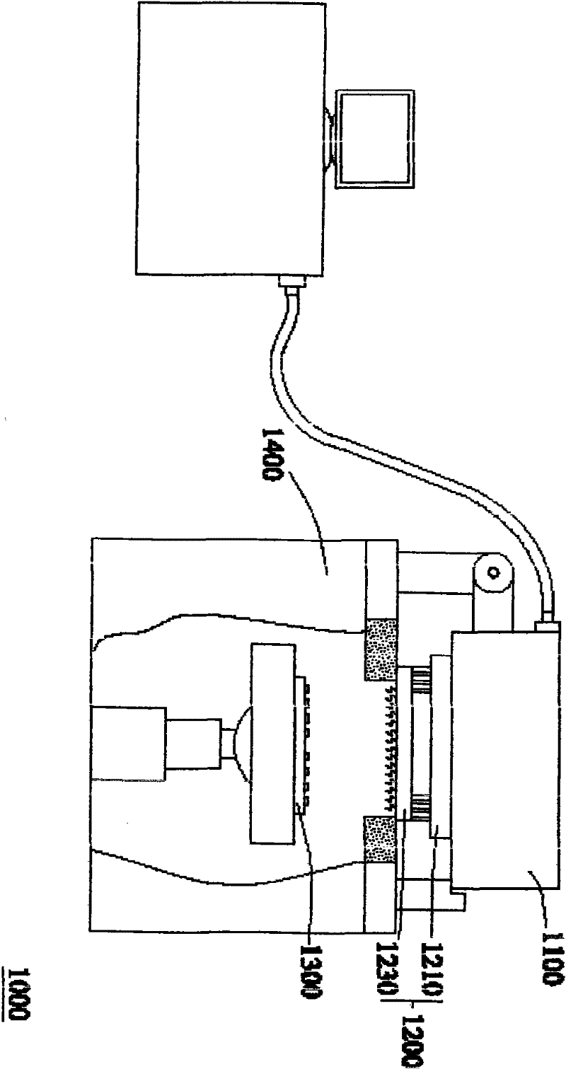
[0041] Please refer to Figure 4A and Figure 4B , Figure 4A Illustrated is a probe system according to a first embodiment of the invention, Figure 4B What is shown is the probe testing device according to the first embodiment of the present invention. The probe testing device 30 is installed on the probe system 2000 , for example. The probe system 2000 includes a test head 2100 , a probe test device 30 , and a wafer tester 2400 . Wherein, the testing machine 2400 includes a carrying platform 2410 , and the device to be tested 2300 is mounted on the carrying platform 2410 . The probe testing device 30 includes: a probe interface board 32 , a space transforming device 34 , a fixed frame 35 , a conductive elastic mechanism 36 , two protection pads 37 , and a vertical probe set 39 .

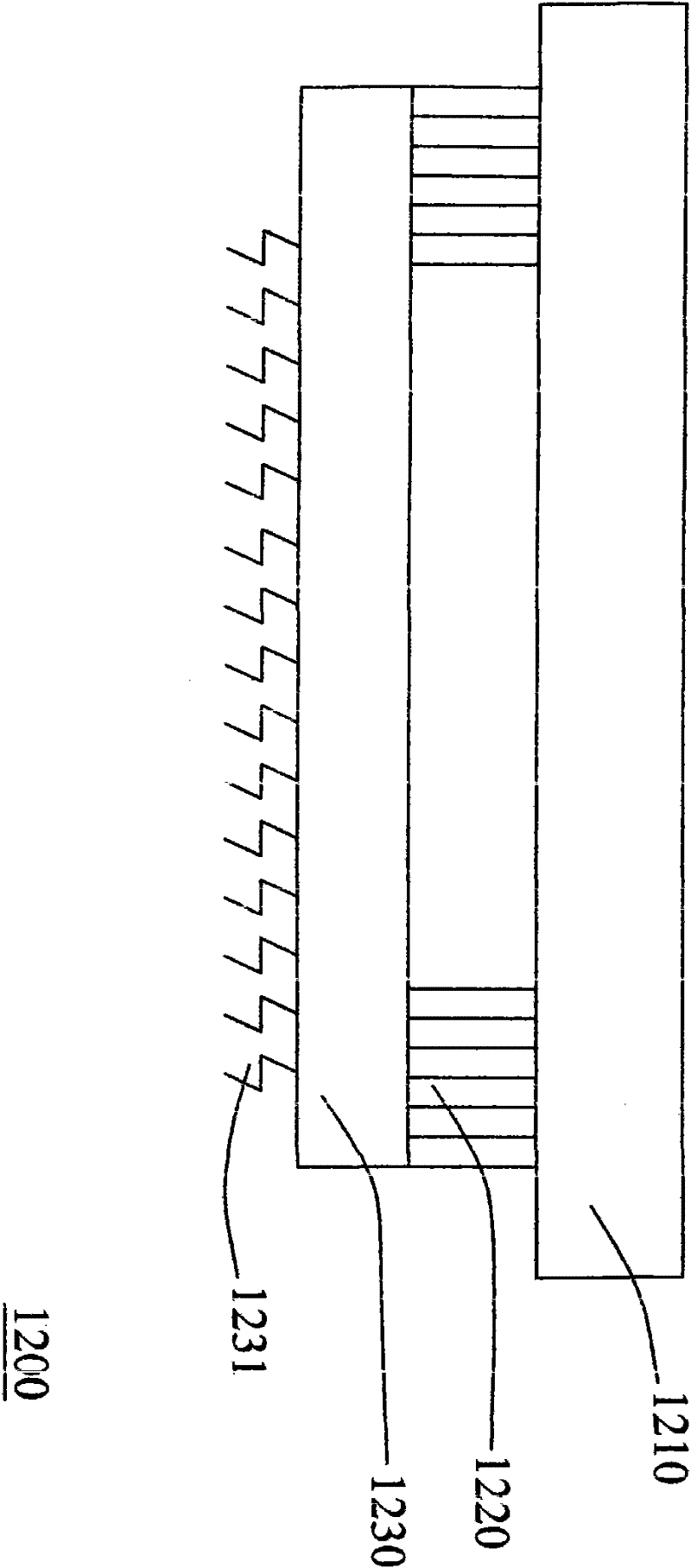
[0042] please compare Figure 1A and Figure 4A ,exist Figure 1A Among them, the probe test device 1200 is connected to the wafer tester 1400 . That is to say, the probe card 1230 of the pr...


PUM


Abstract

The invention relates to a direct probe-testing type probe testing device. The probe testing device comprises a probe interface board, a space converter, a conductive elastic mechanism, a fixed frame and a vertical probe group, wherein the space converter comprises a space conversion board and a reinforcing board; the reinforcing board is electrically connected with the space conversion board; the mechanical strength of the reinforcing board is higher than that of the space conversion board; the conductive elastic mechanism is electrically connected with the probe interface board and the reinforcing board respectively; the fixed frame comprises a reinforcing ring, a frame body and a propping part; the reinforcing ring is arranged on the probe interface board; the conductive elastic mechanism is accommodated in the frame body; the propping part is propped against the space convertor; the vertical probe group comprises a plurality of vertical probes; and the vertical probes are electrically connected with the space conversion board.

Description

technical field [0001] The present invention relates to a probe testing device, in particular to a probe testing device with a longer lifespan and a space transformer plate less easily deformed. Background technique [0002] Please refer to Figure 1A and Figure 1B , Figure 1A Shown is a schematic diagram of a conventional probe system, Figure 1B depicted as Figure 1A Probe test setup in . The probe system 1000 includes a test head 1100 (test head), a probe test device 1200, and a wafer tester 1400 (Prober), and the probe test device 1200 includes a probe interface board 1210 (Probe Interface Board), a pogo tower 1220 (pogo tower), and a probe card 1230 (probe card). Wherein, the probe testing device 1200 is installed on the testing head 1100 . The test signal sent by the test head 1100 will be transmitted to the probe interface board 1210, and then the signal will be transmitted to the device under test 1300 through the vertical probe 1231 on the probe card 1230 aft...

Claims


Application Information

Patent Timeline
Patent Type & Authority Applications(China)
IPC IPC(8): G01R1/067G01R1/073
Inventor 吴坚州陈明祈陈宗毅李忠哲
Owner MPI CORP
Why Eureka
Try Eureka