Magnetic memory including memory cells incorporating data recording layer with perpendicular magnetic anisotropy film
A magnetic memory, anisotropic technology, applied in the direction of digital memory information, static memory, information storage, etc., can solve the problem of weak magnetization in the magnetization fixed area
- Summary
- Abstract
- Description
- Claims
- Application Information
AI Technical Summary
Problems solved by technology
Method used
Image
Examples
no. 1 example
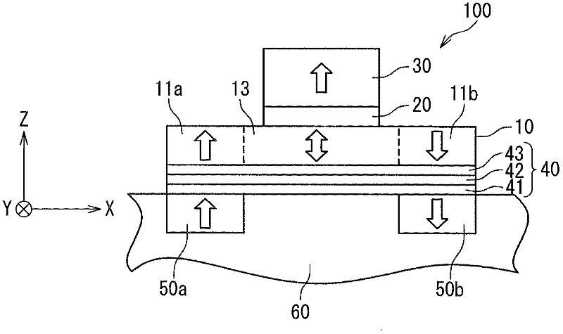
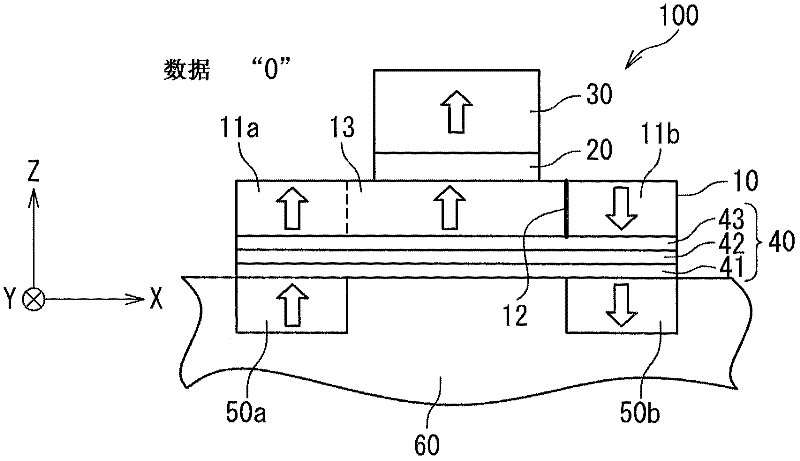
[0071] figure 2 It is a cross-sectional view schematically showing an exemplary configuration of the magnetoresistive element 100 in the first embodiment of the present invention. The magnetoresistance effect element 100 includes a data recording layer 10, a spacer layer 20, a reference layer 30, an underlayer 40, and magnetization fixed layers 50a and 50b.
[0072] The data recording layer 10 is formed of a ferromagnetic material having perpendicular magnetic anisotropy. The data recording layer 10 includes a region in which the magnetization direction can be reversed and data is stored in its magnetization state. In detail, the data recording layer 10 includes a pair of magnetization fixed regions 11 a and 11 b and a magnetization free region 13.
[0073] The magnetization fixed regions 11 a and 11 b are arranged adjacent to the magnetization free region 13. The magnetizations of the magnetization fixed regions 11a and 11b are fixed in opposite directions (or antiparallel). i...
no. 2 example
[0143] Picture 12 It is a cross-sectional view showing a schematic structure of a magnetoresistance effect element 100A of the second embodiment of the present invention. The magnetoresistance effect element 100A of the second embodiment is similar in structure to the magnetoresistance effect element 100 of the first embodiment. The difference lies in the underlying structure. In the first embodiment, as described above, the first magnetic underlayer 41 in the underlayer 40 is formed of an inherent ferromagnetic material, and has a thin thickness such that the first magnetic underlayer 41 does not exhibit ferromagnetism. On the other hand, in the second embodiment, the first magnetic underlayer 41A in the underlayer 40A is formed of a material that inherently exhibits in-plane magnetic anisotropy, but has a feature that makes the first magnetic underlayer 41A exhibit perpendicular magnetic anisotropy. That thickness (specifically, 0.5 to 3 nm). The first magnetic underlayer ...
no. 3 example
[0181] Figure 19A Is a cross-sectional view showing a schematic configuration of a magnetoresistance effect element 100B of the third embodiment of the present invention, and Figure 19B It is a cross-sectional view showing an exemplary configuration of the magnetic recording layer of the magnetoresistance effect element 100B of the third embodiment. It should be noted that Figure 19B Yes Figure 19A The cross-sectional view of the SS' section in.
[0182] The magnetoresistance effect element 100B of the third embodiment is similar in structure to the magnetoresistance effect element 100 of the first embodiment. The difference lies in the underlying structure. In the first embodiment, the underlayer 40 includes a first magnetic underlayer 41, a non-magnetic underlayer 42 and a second magnetic underlayer 43. On the other hand, in the third embodiment, the underlayer 40B does not include components corresponding to the second magnetic underlayer 43 of the first embodiment, but c...
PUM
 Abstract
Description
Claims
Application Information
 - R&D
- Intellectual Property
- Life Sciences
- Materials
- Tech Scout
- Unparalleled Data Quality
- Higher Quality Content
- 60% Fewer Hallucinations
Browse by: Latest US Patents, China's latest patents, Technical Efficacy Thesaurus, Application Domain, Technology Topic, Popular Technical Reports.
© 2025 PatSnap. All rights reserved.Legal|Privacy policy|Modern Slavery Act Transparency Statement|Sitemap|About US| Contact US: help@patsnap.com


