
Method and device for inhibiting eddy current of shield housings of shielded motor

A technology of electric motors and shielding sleeves, which is applied in the direction of electromechanical devices, electrical components, magnetic circuit shape/style/structure, etc., can solve problems such as shielding sleeve rupture, shielding sleeve eddy current power consumption, shielding sleeve deformation, etc., to achieve suppression of eddy current and Eddy current loss, simple structure and process, and the effect of reducing temperature deformation

Inactive Publication Date: 2013-11-06
SHENYANG POLYTECHNIC UNIV
View PDF5 Cites 0 Cited by
  • Summary
  • Abstract
  • Description
  • Claims
  • Application Information

AI Technical Summary

Problems solved by technology

The stator and rotor shielding sleeves of shielded motors are mostly made of metal materials with high pressure resistance, corrosion resistance, high strength, and good thermal conductivity; the rotating magnetic field of the shielded motor will generate eddy current induction potential in the stator and rotor shielding sleeves, forming eddy currents. The eddy current power consumption of the shielding sleeve, so the efficiency of the shielded motor is much lower than that of the ordinary motor with the same power and the same number of poles
At the same time, the eddy current loss of the shielding sleeve will convert electric energy into heat, which will affect the temperature rise of the shielded motor. In particular, the heating of the shielding sleeve will cause the deformation of the shielding sleeve. In severe cases, the shielding sleeve will rupture, resulting in leakage, injury, explosion and other safety accidents.

Method used


Image

  • Method and device for inhibiting eddy current of shield housings of shielded motor
  • Method and device for inhibiting eddy current of shield housings of shielded motor
  • Method and device for inhibiting eddy current of shield housings of shielded motor

Examples


Embodiment Construction

[0020] The specific technical scheme of the present invention will be further described below in conjunction with accompanying drawing and embodiment:

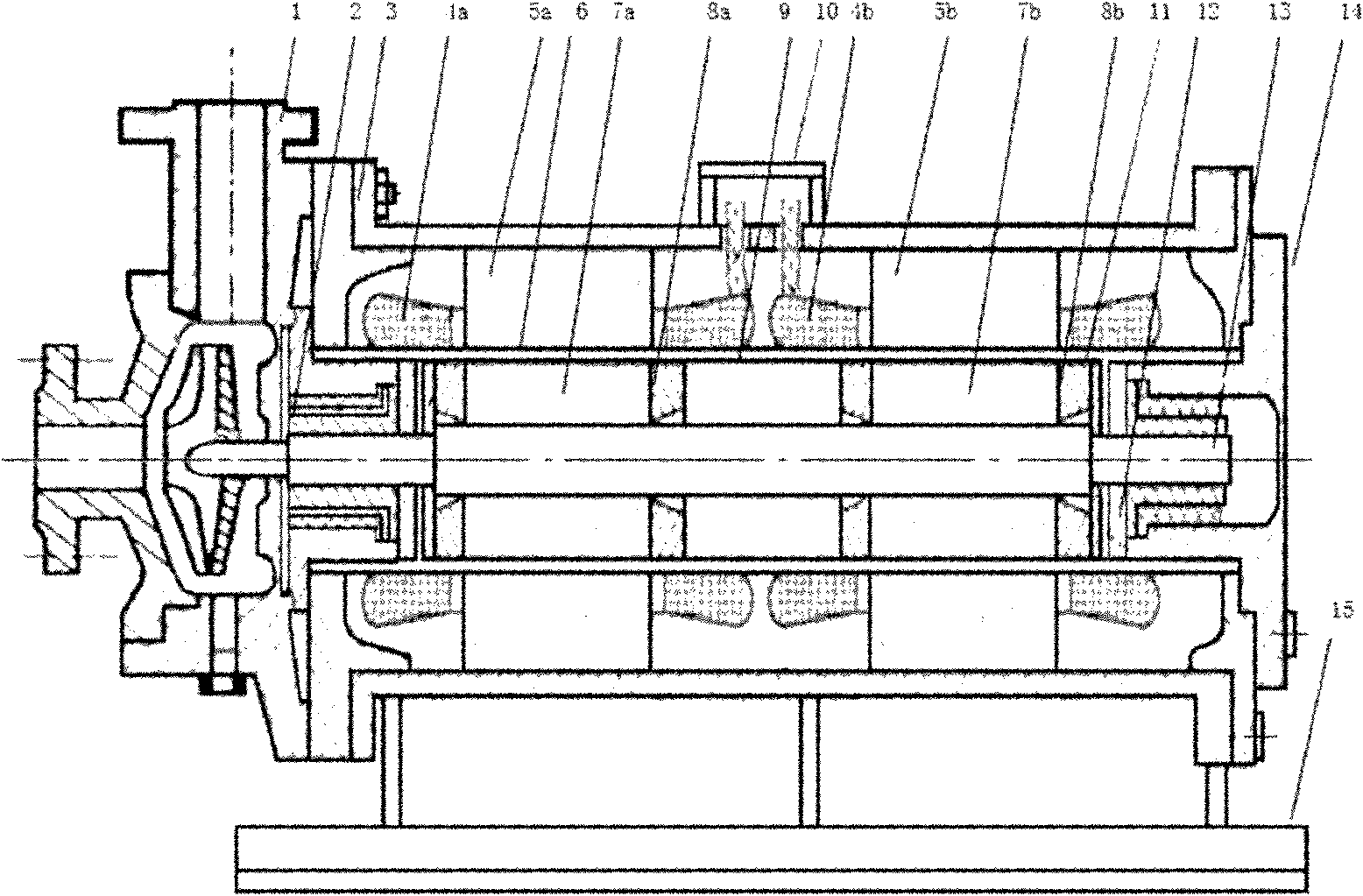
[0021] One embodiment of the present invention is a canned pump motor, such as figure 1 As shown, it mainly consists of pump body 1, bearing 2, housing 3, stator windings 4a and 4b, stator cores 5a and 5b, stator shielding sleeve 6, rotor cores 7a and 7b, rotor windings 8a and 8b, rotor shielding sleeve 9, Junction box 10 , rotor shielding end plate 11 , thrust disc 12 , rotating shaft 13 , end cover 14 and machine base 15 constitute.

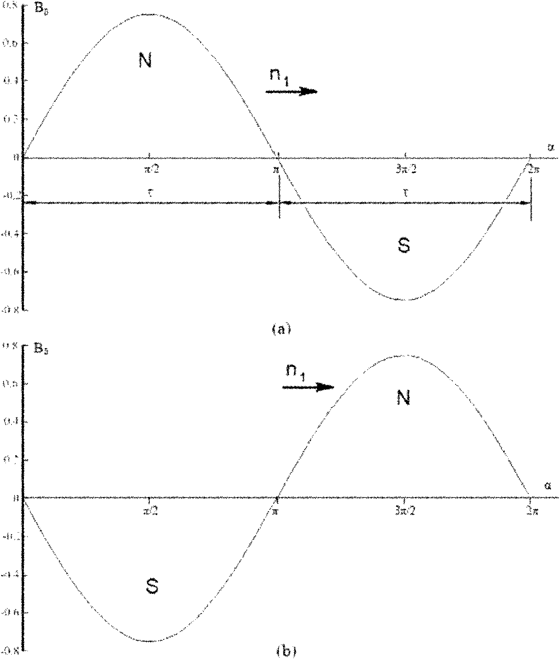
[0022] The stator windings 4a and 4b are identical in structure, wire material, wire specification, forming size and connection mode, and the corresponding phase windings of the stator windings 4a and 4b are staggered by a pole pitch τ=πD in the circumferential direction i1 / (2p), that is, the axis of the stator winding 4a and the axis of the corresponding phase winding of the stator winding 4...


PUM


Abstract

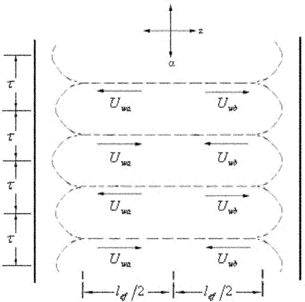
The invention discloses a method and a device for inhibiting eddy current of shield housings of a shielded motor. The method is characterized in that eddy current of the shield housings and eddy current loss are inhibited by mutually offsetting eddy current induced potentials which are formed in the shield housings of the shielded motor and have same size and opposite directions. The device is characterized in that the whole shielded motor comprises two axially-arrayed stators and two coaxially-assembled rotors, wherein the two stators and the two rotors are identical in a structural form and dimension parameters; a polar distance is formed between two stator windings in circumferential space; the two stators share one stator shield housing; and the two rotors share one rotor shield housing. According to the method and the device disclosed by the invention, the eddy current induced potentials can be offset to the maximum extent, so that eddy current and eddy current loss are fundamentally inhibited, the efficiency of the shielded motor can be improved and the aims of reducing consumption and saving energy are achieved. In addition, due to the reduction of the eddy current loss, the reduction of temperature rise is facilitated, the temperature deformation of the shield housings can be reduced and the reliability, the stability and the safety of operation of a shield pump are improved.

Description

technical field [0001] The invention relates to a design technology of a special motor, in particular to a method and a device for suppressing the eddy current of a shielded motor in a shielded motor, and belongs to the technical fields of sealed transmission technology and special motors in power engineering. It is mainly used in the electrical drive of fully sealed devices that require no dynamic seal and no leakage, and can be widely used in shielded electric pumps, magnetic pumps, magnetic stirring reactors, magnetic valves, vacuum magnetic drive equipment, magnetic drive detection instruments and other magnetic forces. transmission system. Background technique [0002] At present, shielded electric pumps and magnetic seal valves, which are mainly used in the fields of nuclear power, military industry, petroleum, chemical industry, refrigeration, medicine, food industry and bioengineering, etc., all need to adopt full-tight measures to protect against corrosive, highly t...

Claims


Application Information

Patent Timeline
Patent Type & Authority Patents(China)
IPC IPC(8): H02K1/06H02K16/00
Inventor 安跃军安辉薛丽萍刘国明温宏亮赵文强
Owner SHENYANG POLYTECHNIC UNIV
Learn More