Switching power control system and method thereof

A technology of switching power supply and control method, which is applied in the direction of control/regulation system, electrical components, and adjustment of electrical variables, etc., which can solve problems such as output voltage drop and achieve simple results

Active Publication Date: 2012-05-30
ACTIONS ZHUHAI TECH CO
View PDF3 Cites 13 Cited by
  • Summary
  • Abstract
  • Description
  • Claims
  • Application Information

AI Technical Summary

Problems solved by technology

Similarly, when the load current is increased instantaneously from a low PWM duty cycle mode, and thus

Method used


Image

  • Switching power control system and method thereof
  • Switching power control system and method thereof
  • Switching power control system and method thereof

Examples


Embodiment Construction

[0026] In the following description, many technical details are proposed in order to enable readers to better understand the application. However, those skilled in the art can understand that without these technical details and various changes and modifications based on the following implementation modes, the technical solution claimed in each claim of the present application can be realized.

[0027] In order to make the purpose, technical solution and advantages of the present invention clearer, the following will further describe the implementation of the present invention in detail in conjunction with the accompanying drawings.

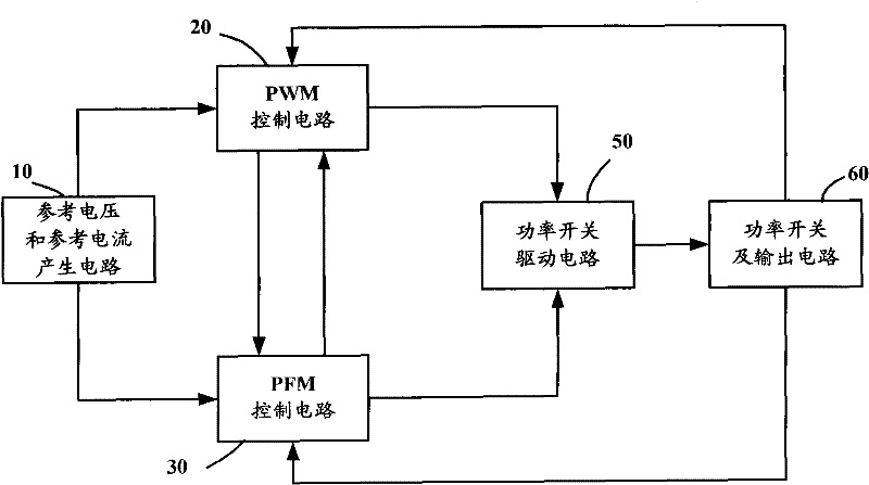
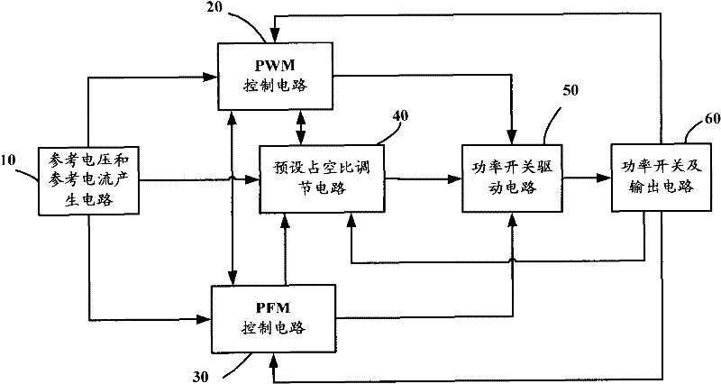
[0028] The first embodiment of the present invention relates to a switching power supply control system. image 3 It is a schematic diagram of the structure of the switching power supply control system. The switching power supply control system includes: a reference voltage and reference current generation circuit 10 , a PWM control circuit 20 , ...


PUM


Abstract

The invention relates to switching power supply technology and discloses a switching power control system and a method thereof. The system comprises a preset duty ratio adjustment circuit used for comparing a voltage feedback signal and a current feedback signal with a received reference voltage signal or reference current signal, determining whether outputs a mode switching signal or not, and outputting a control logic signal to a power switch drive circuit according to a received mode switching signal. Since the control logic signal outputted by the preset duty ratio adjustment circuit can be a control logic signal with a higher conduction duty ratio directly, when load current is increased instantaneously, the control logic signal outputted by the preset duty ratio adjustment circuit can be directly outputted to the power switch drive circuit without waiting for that a PWM control circuit is adjusted from a low conduction duty ratio to a high conduction duty ratio slowly, thus actual output voltage of a switching power supply is raised rapidly, transient response of a load is improved, and influence on normal work of electronic equipment is avoided.

Description

technical field [0001] The invention relates to switching power supply technology, in particular to transient response in switching power supply technology. Background technique [0002] Due to the increasing popularity of portable consumer electronic products, the switching power supply technology of portable electronic devices has been developed rapidly. Switching power supplies usually have two working modes: pulse width modulation (Pulse Width Modulation, "PWM" for short) and pulse frequency modulation (Pulse Frequency Modulation, "PFM" for short). [0003] In the PWM working mode, the switching power converter works at a constant switching frequency, and the PWM control circuit gradually adjusts the conduction time of the power switch according to the load condition. Usually in PWM mode, the switching power supply has a strong load capacity. Higher efficiencies can be achieved at heavy loads, while constant switching losses degrade efficiency at light loads. [0004]...

Claims


Application Information

Patent Timeline
IPC IPC(8): H02M3/158
CPCY02B70/16H02M2001/0032H02M3/155H02M1/0032Y02B70/10
Inventor 刘永根熊江肖丽荣
Owner ACTIONS ZHUHAI TECH CO
Why Eureka
Try Eureka