System and method for realizing remote disaster recovery of optical line terminal (OLT)

A remote disaster recovery and relational technology, applied in the field of passive optical network, can solve problems such as difficult service switching, inability to connect uplink ports, increase fault points, etc., and achieve the goals of saving interconnection fibers, complete protection measures, and speeding up service recovery Effect

Active Publication Date: 2012-05-30
深圳市中兴通讯技术服务有限责任公司
View PDF8 Cites 18 Cited by
  • Summary
  • Abstract
  • Description
  • Claims
  • Application Information

AI Technical Summary

Problems solved by technology

Patent 200710166383.X also provides a backup method for OLT equipment, by configuring the backup group, and realizing the protection and backup of the trunk path through the notification message and backup message between the OLTs, due to the need to report between the OLT Text exchange, the message channel between the active and standby OLTs increases the cost and the point of failure, and it is difficult to achieve fast service switching. In addition, the active and standby switching of this patent only considers the abnormality of the main fiber, and cannot be connected with the uplink Linkage
[0005] In addition, patent 201010142584.8 also mentions a method of using Bidirectional Forwarding Detection (BFD, Bidirectional Forwarding Detection) on the provider edge equipment (PE, Provider Edge) to detect the status of the uplink pseudowire and associate it with the downlink user equipment (CE, Customer Equipment) Connectivity linkage between CE side and PE side to improve service reliability, but this patent only provides a fault detection and service association idea, and cannot realize cross-OLT protection function

Method used


Image

  • System and method for realizing remote disaster recovery of optical line terminal (OLT)
  • System and method for realizing remote disaster recovery of optical line terminal (OLT)
  • System and method for realizing remote disaster recovery of optical line terminal (OLT)

Examples


Embodiment Construction

[0032] Below, refer to the attached Figure 1-9 The system and method for realizing OLT remote disaster recovery of the present invention are described in detail.

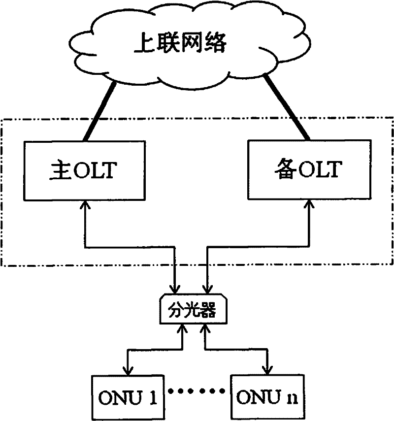
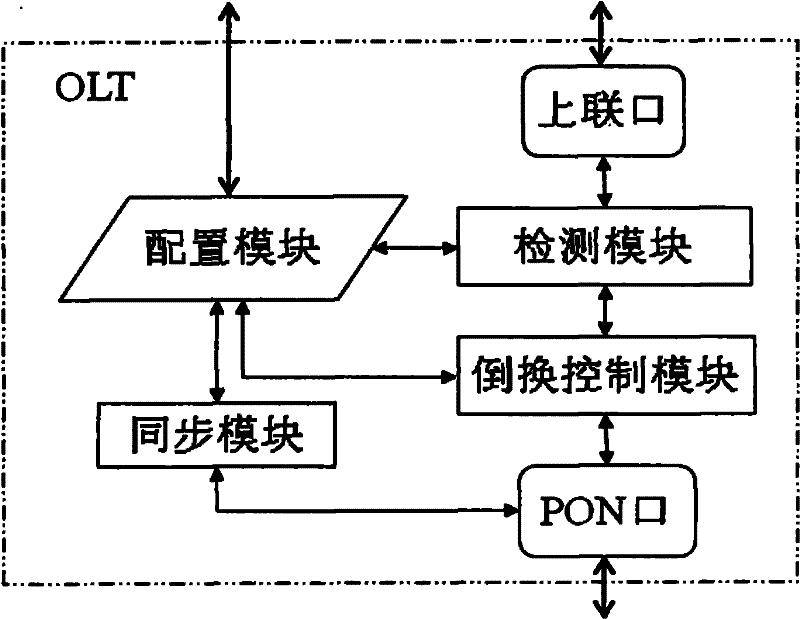
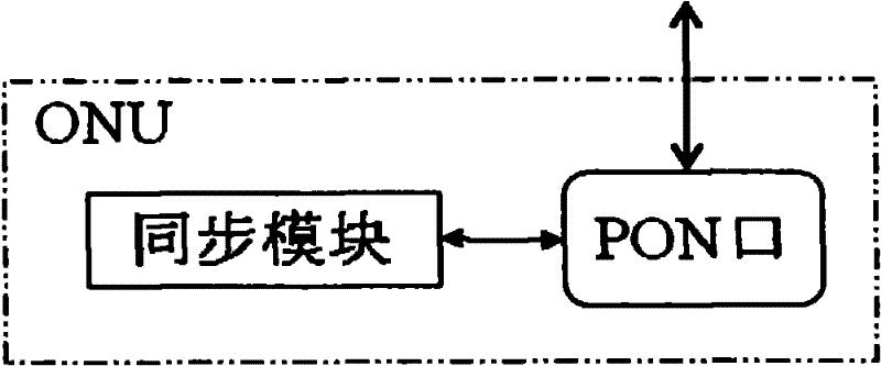
[0033] The system for implementing OLT remote disaster recovery of the present invention includes an optical network unit (ONU, Optical Network Unit), an optical splitter node, and at least two optical line terminal OLTs. The OLT is a Gigabit-capable Passive Optical Network (GPON) OLT. Networking such as figure 1 shown. Each OLT has a PON port connected to the optical splitter, and the ONU is connected to the branch optical path of the optical splitter. The two PON ports of the OLT are configured in the protection group. Under normal working conditions, one of the PONs works as Master (main) , the working state of the other PON port is Standby (slave), and the ONU acts as a bridge between the master and slave PON to realize configuration data synchronization. In addition, the slave PON port maintains the registr...


PUM


Abstract

The invention provides a system and a method for realizing remote disaster recovery of optical line terminals (OLT), wherein an optical network unit (ONU) in the system communicates with a main OLT and at least one spare OLT through an optical splitter node. A synchronizing module is arranged on the main OLT for sending current configuration information and ONU relevant parameters to corresponding ONU and further for ignoring configuration information and ONU relevant parameters. A synchronizing module is arranged on the spare OLT for extracting configuration information and current ONU relevant parameters so as to synchronize with the configuration information and ONU relevant parameters of the main OLT. The ONU comprises a synchronizing module for receiving the configuration information and ONU relevant parameters and transmitting the configuration information and ONU relevant parameters to the main OLT and the spare OLT. The invention realizes information interaction between the main OLT and the spare OLT through the ONU so as to avoid establishment of an additional information channel between the main OLT and the spare OLT, thereby saving interconnected optical fibers between the main OLT and the spare OLT.

Description

technical field [0001] The present invention relates to a passive optical network (PON, Passive Optical Network) technology, in particular to a system and method for realizing remote disaster recovery of an optical line terminal (OLT, Optical Line Terminal) in a passive optical network. Background technique [0002] With the rapid growth of the access network's demand for service bandwidth, the development of optical communication technology and the reduction of costs, optical fiber communication is transparent to services, long in life, almost unlimited in bandwidth carrying capacity, and can adapt to growing bandwidth and new business development needs. It has become an important way of network construction at the access layer, "optical into copper retreat", optical nodes are gradually moved down, fiber to the premises (FTTP, Fiber To The Premise), fiber to the building (FTTB, Fiber To The Building), Fiber to the office (FTTO, Fiber To The Office) and fiber to the home (FT...

Claims


Application Information

Patent Timeline
Patent Type & Authority Applications(China)
IPC IPC(8): H04B10/12H04Q11/00H04L1/22H04L12/56H04B10/032H04L45/586
CPCH04Q2011/0081H04Q11/0067H04B10/032
Inventor 陈必多李明生卢金树
Owner 深圳市中兴通讯技术服务有限责任公司
Why Eureka
Try Eureka