Rotating electric machine comprising an exciter

An exciter, rotary technology used in synchronous motors for single-phase current, control generators, synchronous generators, etc., to solve problems such as reduction in available power

Inactive Publication Date: 2012-05-30
MOTEURS LEROY SOMER
View PDF8 Cites 3 Cited by
  • Summary
  • Abstract
  • Description
  • Claims
  • Application Information

AI Technical Summary

Problems solved by technology

However, this value of the pitch leads to...

Method used


Image

  • Rotating electric machine comprising an exciter
  • Rotating electric machine comprising an exciter
  • Rotating electric machine comprising an exciter

Examples


Embodiment Construction

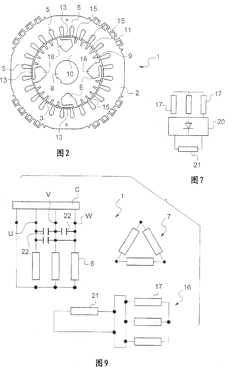
[0097] will refer to figure 2 A three-phase rotating electrical machine 1 according to an exemplary embodiment of the present invention will be described.

[0098] The three-phase electric machine 1 is, for example, a synchronous machine used as an alternator and has, for example, a power in the range between 5-1000 kVA.

[0099] In the example shown, the machine 1 comprises a stator yoke 2 and a rotor yoke 3 .

[0100] The stator yoke 2 and the rotor yoke 3 house the main electrical winding and the exciter electrical winding, respectively.

[0101] Such as figure 2 As can be seen in , the stator yoke 2 can comprise a plurality of slots 5 evenly distributed around the circumference. In the example described, the stator yoke 2 comprises twenty-four slots 5 , but the invention is not limited to a specific number of slots 5 .

[0102] image 3 An example of a main armature winding 6 housed in a slot 5 is shown. image 3 , Figure 8 , Figure 12 and Figure 14 Shows the...


PUM


Abstract

The present invention relates to a three-phase rotating electric machine, comprising a stator and a rotor each comprising an exciter electric winding and a main electric winding, the exciter winding of the stator (respectively of the rotor) being three-phase and comprising a number of poles equal to that of the main winding of the stator (respectively of the rotor), the said exciter winding of the stator (respectively of the rotor) being connected in a triangle to form a single-phase winding comprising a number of poles which is a multiple of three of that of the main armature winding of the stator (respectively of the rotor).

Description

technical field [0001] The subject of the invention is a three-phase rotating electrical machine to be connected to a three-phase distribution system and comprising an at least partially self-powered exciter. Background technique [0002] Figure 1a and Figure 1b Shows a known solution of a polyphase rotating electrical machine with an exciter based on two separated machines, the main machine 100 comprising a stator 101 and a pole wheel 102 and an exciter 103 consisting of The exciter inductor on 104 and the exciter armature, including smooth poles, wound on the rotor 105. [0003] Using eg two machines assembled axially results in a relatively bulky system. [0004] Furthermore, the axial entry of air would then be blocked by the machine forming the exciter, thus detrimental to the cooling of the host machine. [0005] The electromotive force induced by the third harmonic of the magnetic field within the air gap associated with the main winding affects the form of volta...

Claims


Application Information

Patent Timeline
IPC IPC(8): H02P9/10H02P9/30H02K11/04H02K19/12H02K19/26H02K19/28
CPCH02K3/28H02P9/10H02P9/102H02K19/38H02P9/305H02P9/30
Inventor 弗朗索瓦・柴可夫斯基弗洛朗・比勒米歇尔・勒纳尔
Owner MOTEURS LEROY SOMER
Why Eureka
Try Eureka