

Optical fiber type high-precision tension detection device
A tension detection, high-precision technology, applied in the field of sensing, can solve the problems of limiting the range of use of electronic tension sensing devices, not being able to use it for a long time, and difficulty in precision, and achieve the benefits of popularization and use, good use effect, and high test accuracy Effect
- Summary
- Abstract
- Description
- Claims
- Application Information
AI Technical Summary
Problems solved by technology
Method used
Image

Examples
Embodiment 1
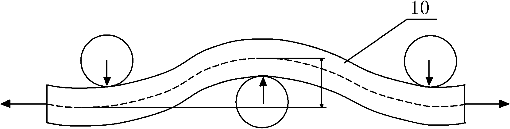
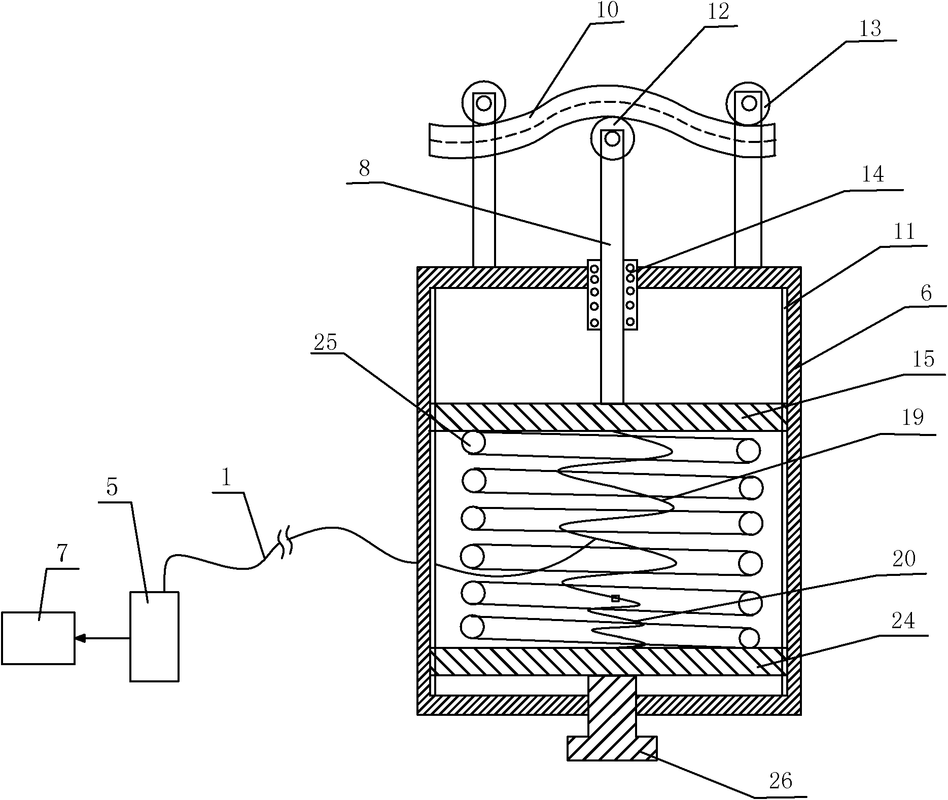
[0041] Such as figure 2 and 3 An optical fiber type high-precision tension detection device shown includes a housing 6 and a pulley 13 arranged above the housing 6. The number of the pulleys 13 is three, and two of the pulleys 13 are arranged on both sides and Both are fixedly connected to the housing 6 through a fixed rod, the other of the pulleys 13 is an intermediate pulley 12, the intermediate pulley 12 is located between the two pulleys and fixed on the upper end of the transmission rod 8, and the transmission rod 8 is installed on the housing 6, the transmission rod 8 is slidingly matched with the housing 6, the lower end of the transmission rod 8 is located inside the housing 6, and an optical fiber bending sensing unit is also arranged inside the housing 6, and the optical fiber bending sensing unit is located at The lower end of the transmission rod 8, the optical fiber bending sensing unit includes a signal fiber 33, a curved test channel for the signal fiber 33 to...
Embodiment 2
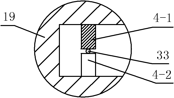
[0045] Such as Figure 4 and 5 As shown, the difference between this embodiment and Embodiment 1 is that the curved support 19 is a spring, and the first deformed tooth 4-1 and the second deformed tooth 4-2 are correspondingly arranged between two adjacent coils of the spring wire of the linear support 19. Between, and deformed teeth 1 4-1 and deformed teeth 2 4-2 are alternately arranged. In this embodiment, the structures, connections and working principles of other parts are the same as those in Embodiment 1.
Embodiment 3
[0047] Such as Figure 6 and 7 As shown, the difference between this embodiment and Embodiment 1 is that the curved bracket 19 is a bellows, and the first deformed tooth 4-1 and the second deformed tooth 4-2 are correspondingly arranged in the inner recess on the pipe wall 41 of the bellows On the opposite two side surfaces of each other, the first deformed tooth 4-1 and the second deformed tooth 4-2 are arranged alternately. In this embodiment, the structures, connections and working principles of other parts are the same as those in Embodiment 1.
PUM
 Abstract
Description
Claims
Application Information