Method, device and equipment for colloid removal with laser

A laser and laser energy technology, applied in laser welding equipment, welding equipment, metal processing equipment, etc., can solve the problems of insufficient cutting yield, time-consuming, etc., and achieve the effect of improving production efficiency and reducing production defect rate

Inactive Publication Date: 2012-06-13
SHENZHEN MUSEN TECH
View PDF8 Cites 20 Cited by
  • Summary
  • Abstract
  • Description
  • Claims
  • Application Information

AI Technical Summary

Problems solved by technology

[0004] In the process of making the PCB board, when the electronic components inserted on the PCB board are found to be defective, they need to be removed and

Method used


Image

  • Method, device and equipment for colloid removal with laser
  • Method, device and equipment for colloid removal with laser
  • Method, device and equipment for colloid removal with laser

Examples


Embodiment Construction

[0032] In order to describe the technical content, structural features, achieved goals and effects of the present invention in detail, the following will be described in detail in conjunction with the embodiments and accompanying drawings.

[0033] Laser processing technology is a technology that uses the characteristics of the interaction between the laser beam and the material to cut, weld, surface treat, drill, micro-process, and use it as a light source to identify objects, etc., for materials (including metals and non-metals). The largest field is laser processing technology. Laser processing systems include lasers, light guide systems, processing machine tools, control systems and detection systems.

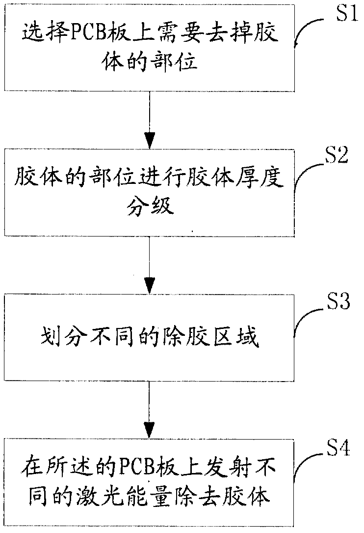
[0034] see figure 1 , a laser deglue method, comprising:

[0035] S1. Select the part on the PCB where the colloid needs to be removed;

[0036] When removing bad components, such as IC, the colloid still remains on the PCB, you can scan the colloid, take a photo and tran...


PUM


Abstract

The invention discloses a method for colloid removal with laser, which comprises S1 selecting portions where colloid needs removing on a printed circuit board (PCB), S2 grading colloid thickness of the colloid portions, S3 dividing into different colloid removal areas according to grading of different thickness, and S4 emitting different amounts of laser energy or number of laser scanning to the PCB to remove colloid. The invention further discloses a device and a system for colloid removal with laser. The method and the device achieve colloid removal with a purely physical method, are environment-friendly and free of chemical pollution, save time and labor, and greatly improve production efficiency.

Description

technical field [0001] The invention relates to the field of laser equipment, in particular to a laser glue removal method, device and equipment. Background technique [0002] Printed circuit board, also known as printed circuit board, printed circuit board, referred to as printed board, English referred to as PCB (printed circuit board) or PWB (printed wiring board), with insulating board as the base material, cut into a certain size, on it At least one conductive pattern is attached, and holes (such as component holes, fastening holes, metallized holes, etc.) are used to replace the chassis of the previous electronic components and realize the interconnection between electronic components. The via hole can make the lines of more than two levels conduct with each other, and the larger via hole is used as a part plug-in. In addition, there are non-conducting holes (nPTH) which are usually used for surface mount positioning and fixing screws during assembly. , There are many...

Claims


Application Information

Patent Timeline
IPC IPC(8): B23K26/36
Inventor 彭信翰
Owner SHENZHEN MUSEN TECH
Why Eureka
Try Eureka