Alloy melt purifier and its method

A melt purification and alloy technology, applied in the field of alloy melt processing, can solve the problems of unfavorable overall uniform degassing of molten pools, high usage of inert gas, low degassing efficiency, etc., so as to improve degassing purification efficiency and reduce coil The effect of increasing the entry and contact area

Active Publication Date: 2012-06-13
NORTHEASTERN UNIV LIAONING
View PDF2 Cites 12 Cited by
  • Summary
  • Abstract
  • Description
  • Claims
  • Application Information

AI Technical Summary

Problems solved by technology

However, there are some problems: polluting the environment, releasing corrosive and toxic gases when refining alloys with solvents or active gases; the size of the bubbles formed in the melt is relatively large, about 10 mm, so the degassing efficiency is low and the degassing time is long , about 10-20 minutes; the amount of inert gas used is high, even with the SNIF and ALPURUR technologies with better degassing effects, the ratio of gas consumption to metal has reached 0.67-0.84L / kg; The eddy current makes the liquid level fluctuate seriously, resulting in increased oxidation, which is not conducive to the overall uniform degassing inside the molten pool

Method used


Image

  • Alloy melt purifier and its method
  • Alloy melt purifier and its method
  • Alloy melt purifier and its method

Examples


Embodiment 1

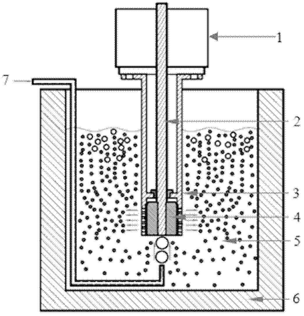
[0031] Use the device of the present invention to carry out degassing and purification treatment on 7075 aluminum alloy. The material connecting shaft 2, stator 3 and rotor 4 in the device is Sialon ceramics. The gap between 3 and rotor 4 is set to 200 μm, and the cross-sectional area of ​​the hole opened on the lower end wall of stator 3 is 4 mm 2 , the melting temperature of the aluminum alloy melt 5 is 750°C, first, preheat the device to 650°C-710°C; extend the stator 3 of the alloy melt purification device into the heat preservation container 6 below the liquid level of the alloy melt 5 to be treated 50 mm position; feed argon gas into the alloy melt 5 below the rotor 4, the pressure of the argon gas is controlled at 0.15MPa, and the flow rate is 1L / min; the motor is started to drive the rotor 4 to rotate, and the speed of the rotor 4 gradually increases from the initial high speed. Switch to medium-speed and low-speed operation; purify for 60s, stop feeding argon, turn of...

Embodiment 2

[0041] Utilize the device of the present invention to carry out degassing and purification treatment on A356 aluminum alloy. The device structure setting, degassing and purification process and the measurement process of the cleanliness of the alloy melt 5 in this embodiment are basically the same as those in Embodiment 1, and the difference is connected in the device. Shaft 2, stator 3 and rotor 4 are made of molybdenum with MoSi2 coating, and the cleaning time is 90s;

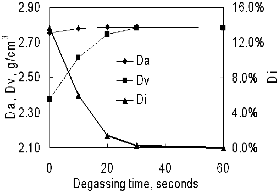
[0042] The density and density index of the A356 aluminum alloy melt 5 during the degassing purification process vary with the purification time as shown in Image 6 As shown, it can be seen from the figure that after 60 seconds of purification, the density index of A356 aluminum alloy can be reduced to less than 1%;

[0043] The comparison of the degassing effect of the device and method of the present invention with the conventional alloy melt degassing purification method for processing the A356 aluminum a...


PUM

PropertyMeasurementUnit
areaaaaaaaaaaa
porosityaaaaaaaaaa

Abstract

The invention relates to an alloy melt purifier and its method, the purifier comprises a driving motor, a connection shaft, a stator and a rotor. The driving motor is directly connected with the connection shaft, the end portion of the connection shaft enables fixed connection with the rotor, the connection shaft and the rotor are arranged in the columnar stator, the stator is embedded and fixed in an insulation container, the alloy melt is filled in the insulation container, the stator is immersed in the alloy melt, an aperture is opened on the wall at the lower part of the stator, a vapor pipe is provided at one side of the insulation container, a gas outlet of the vapor pipe is in alignment with the lower part of the lower part of the rotor; The method for purifying the alloy melt by using the purifier comprises the following steps: the alloy melt and inert gas are sucked in the purifier through the high speed rotation of the rotor, high strength shearing effect formed by the stator and the rotor can be used, and the controllable forced convection can be generated under the liquid surface of the alloy melt, thereby the introduced inert gas bubbles can be smashed to fine bubbleswhich are uniformly distributed in the melt, the fine inert gas bubbles absorb impure gas in the melt and overflow the liquid surface, so that the purification of the melt with high efficiency can berealized.

Description

technical field [0001] The invention belongs to the technical field of alloy melt treatment, and in particular relates to an alloy melt purification device and method. Background technique [0002] The purification of aluminum alloy melt is the key technology to ensure its metallurgical quality, and reducing the hydrogen content in the melt is the main purpose of aluminum melt purification. During the smelting process, aluminum alloy is very sensitive to hydrogen or water vapor, and it will inevitably absorb a certain degree of hydrogen. If the melt is cast without treatment (die casting or continuous casting), defects such as porosity and porosity will occur, and may cause hot cracking of ingots or castings, thereby increasing the scrap rate. Therefore, on the one hand, the introduction of hydrogen should be minimized during the smelting process; on the other hand, the melt should be degassed and purified before casting. Degassing treatment usually also has the effect of ...

Claims


Application Information

Patent Timeline
Patent Type & Authority Applications(China)
IPC IPC(8): C22B9/05C22B21/06C22C1/06C22C21/00
Inventor 左玉波樊中云崔建忠
Owner NORTHEASTERN UNIV LIAONING
Why Eureka
Try Eureka