Construction method of equipment foundation reserved square hole

A technology of equipment foundation and construction method, which is applied in basic structure engineering, formwork treatment, formwork/formwork/work frame, etc., can solve the problems of inability to meet the needs of large upper and lower lower openings, difficult force, inconvenient removal, etc. Achieve the effect of reducing labor intensity, improving pull-out bearing capacity, and reducing construction costs

Active Publication Date: 2012-06-13
CHINA FIRST METALLURGICAL GROUP
View PDF4 Cites 1 Cited by
  • Summary
  • Abstract
  • Description
  • Claims
  • Application Information

AI Technical Summary

Problems solved by technology

The steel corrugated pipe adopts a tool with a slot at one end and a handle at the other end. The slot is clamped to the steel bellows, and the steel corrugated pipe is peeled off layer by layer. The removal effect is not satisfactory; the plastic pipe is baked at high temperature to make it soft, and then Pulling out as a whole, the method sometimes causes the plastic pipe to break off, which directly affects the strength of the secondary grouting of the anchor bolt holes; the wooden formwork adopts a square pyramid-shaped wooden box structure with a large upper opening and a smaller lower opening, with small cross-section and deep depth. For deep holes, there will be various difficulties such as difficulty in force and limited space when dismantling
In order to improve the pull-out bearing capacity of bolts, a structure with the lower opening slightly larger than the upper opening is often used. Steel bellows and plastic pipes are standard materials for pipe diameters, which cannot meet the requirements of large upper openings and smaller lower openings. The upper opening is smaller than the lower opening. The large pyramid-shaped wooden box cannot be dismantled even if it meets the size requirements
Namely: the anchor bolt hole is characterized by a long and narrow space with a large aspect ratio, so it brings great inconvenience to the demolition, and its formwork cannot be reused during the demolition process

Method used


Image

  • Construction method of equipment foundation reserved square hole
  • Construction method of equipment foundation reserved square hole
  • Construction method of equipment foundation reserved square hole

Examples


Embodiment Construction

[0024] In order to better understand the present invention, the technical solutions of the present invention will be further described below in conjunction with the embodiments and the accompanying drawings.

[0025] The construction method for reserved square holes in the equipment foundation includes the following steps:

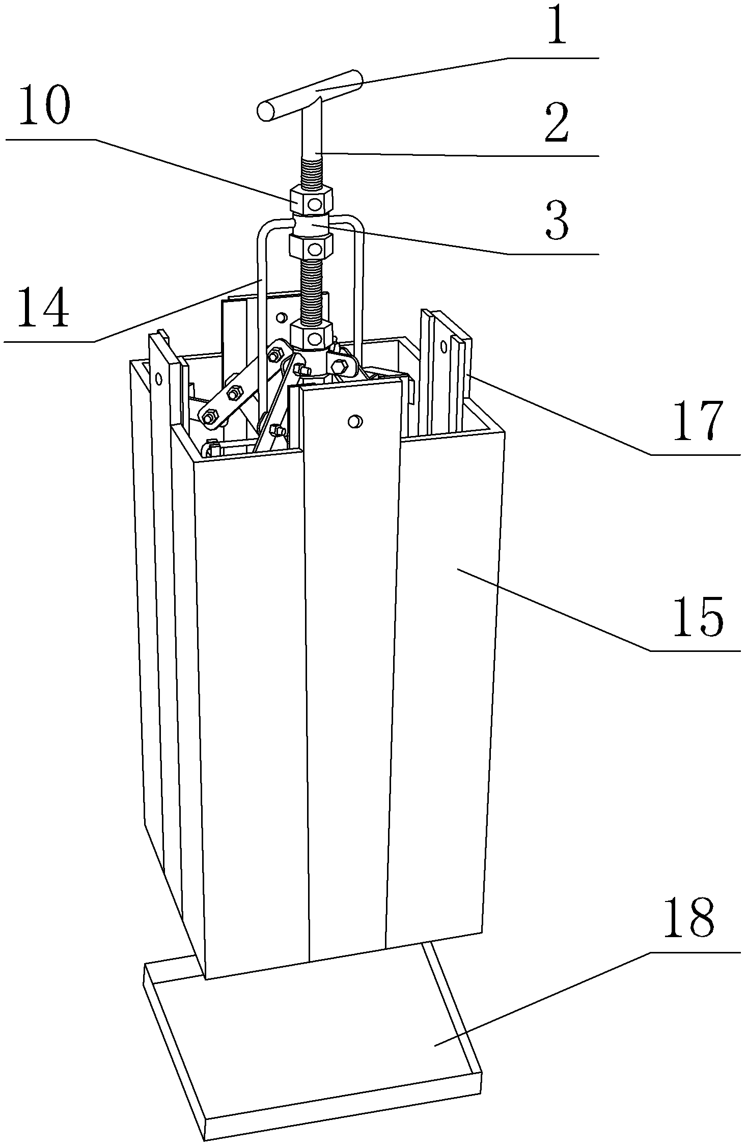
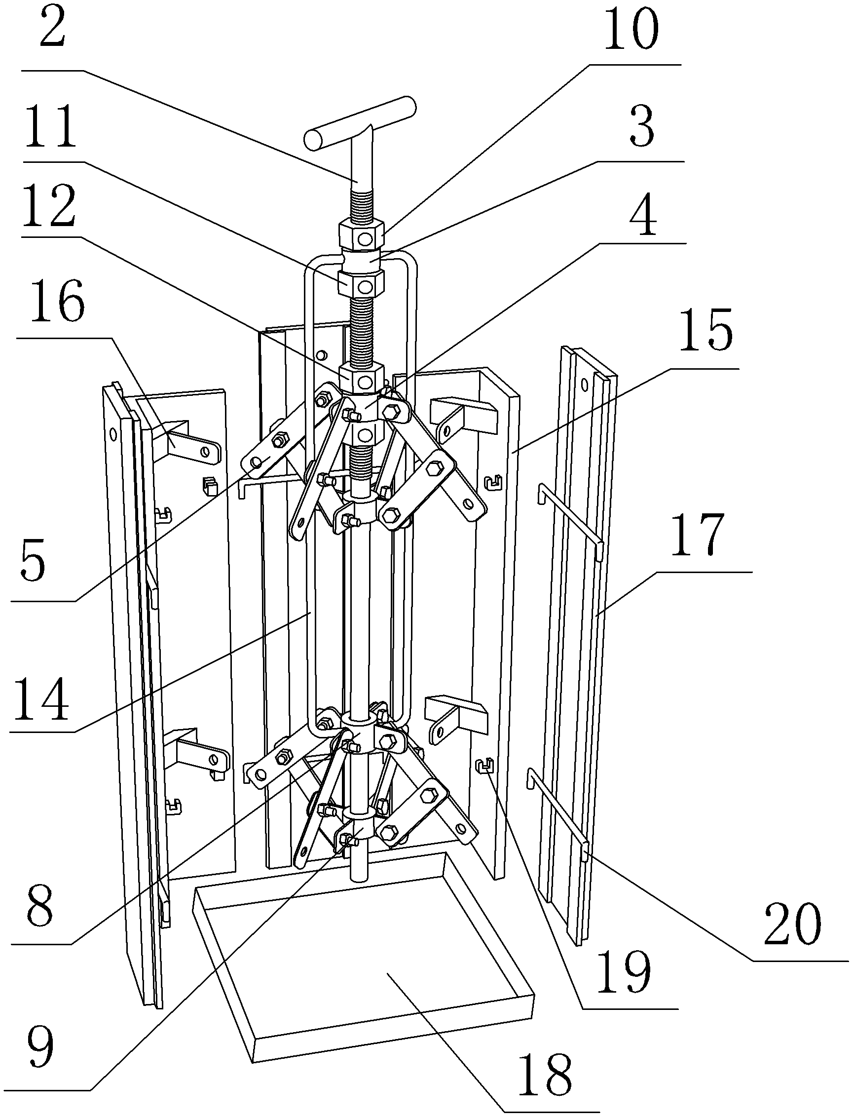
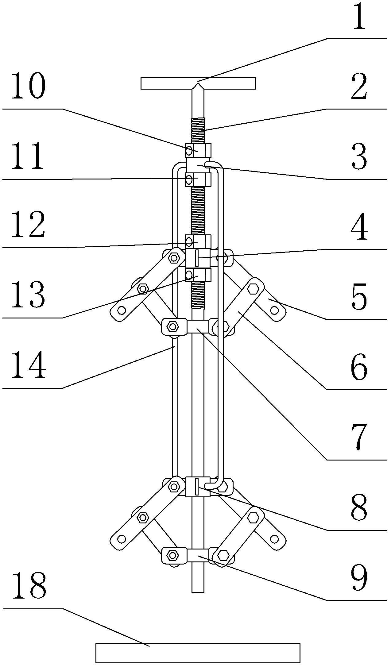
[0026] The first step is to assemble the mold: a reusable mold with square holes reserved in the equipment foundation, its structure is as follows Figure 1 to Figure 3 As shown, it includes a central axis 2, a first expansion and contraction device, a second expansion and contraction device, 4 corner templates 15, and 4 middle templates 17; 4 corner templates 15 are L-shaped at right angles, 4 The three corner templates 15 are distributed at 4 corners, the middle template 17 is inserted between the corner templates and the corner templates on the same side, the space surrounded by 4 corner templates 15 and 4 middle templates 17, 4 corner templates 15 Two...


PUM


Abstract

The invention belongs to a construction method of an equipment foundation reserved square hole. The construction method of the equipment foundation reserved square hole is characterized by comprising the following steps: first step, assembling a die; second step, erecting the die: adjusting the dimensions of an upper opening of the reusable die of the equipment foundation reserved square hole, unscrewing a fourth positioning nut, moving a second sliding adjustment seat downwards to reach the rectangular dimensions of a corner die plate upper opening, unscrewing a second positioning nut, moving a first sliding adjustment seat downwards to reach the rectangular dimensions of an corner die plate lower opening, then screwing a third positioning nut and a first positioning nut, and taking a plastic film or a binding tape as a protective layer of the die plate to wrap up on the outside walls of the corner die plate and a middle die plate; third step, pouring concrete; fourth step, removing the die plates, extracting the corner die plate and leaving a square hole opening; and fifth step, cleaning the hole opening to obtain the equipment foundation reserved square hole. The method is simple to operate and is fast in die removal, and the die can be reused.

Description

technical field [0001] The invention belongs to a construction method for reserved square holes (reserved square holes for anchor bolts) in equipment foundations. Background technique [0002] In the construction of the equipment foundation, the foundation bolt holes of the equipment need to be reserved on the concrete foundation. The reserved method generally adopts the methods of supporting steel bellows, plastic pipes or supporting wooden formwork, etc., and removes them in time after the concrete solidifies. The steel corrugated pipe adopts a tool with a slot at one end and a handle at the other end. The slot is clamped to the steel bellows, and the steel corrugated pipe is peeled off layer by layer. The removal effect is not satisfactory; the plastic pipe is baked at high temperature to make it soft, and then Pulling out as a whole, the method sometimes causes the plastic pipe to break off, which directly affects the strength of the secondary grouting of the anchor bolt...

Claims


Application Information

Patent Timeline
Patent Type & Authority Applications(China)
IPC IPC(8): E02D27/44E04G15/04E04G19/00
Inventor 王平夏春
Owner CHINA FIRST METALLURGICAL GROUP
Why Eureka
Try Eureka