
Force measuring apparatus of jet vane carried engine hot firing test

A force measuring device and gas rudder technology, applied in the direction of gas turbine engine testing, jet engine testing, measuring devices, etc., can solve problems such as poor versatility, difficulty in realizing complex test conditions and accurate simulation, and low measurement accuracy, and achieve accurate deflection , reliable heat protection device, and strong versatility

Active Publication Date: 2012-06-13
CHINA ACAD OF AEROSPACE AERODYNAMICS
View PDF4 Cites 23 Cited by
  • Summary
  • Abstract
  • Description
  • Claims
  • Application Information

AI Technical Summary

Problems solved by technology

Due to the lack of gas rudder applications in the past, there were not many force tests carried out on hot test vehicles equipped with engines. Usually, a simple and special test device was developed for a specific model to realize the force measurement of gas rudders under typical conditions. Its structure is usually Relatively simple, it is difficult to realize complex test conditions and accurate simulation, the measurement accuracy is not high, and the versatility is poor

Method used


Image

  • Force measuring apparatus of jet vane carried engine hot firing test
  • Force measuring apparatus of jet vane carried engine hot firing test
  • Force measuring apparatus of jet vane carried engine hot firing test

Examples


Embodiment Construction

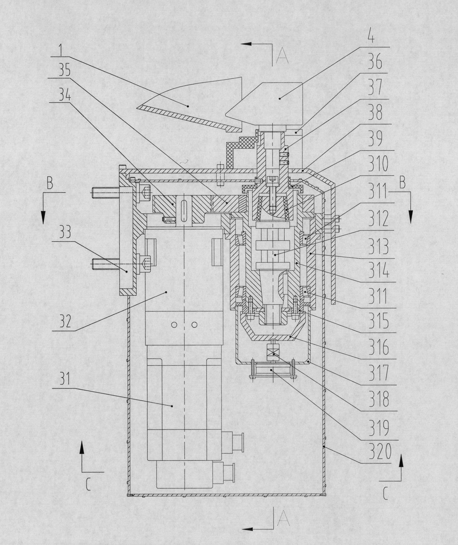
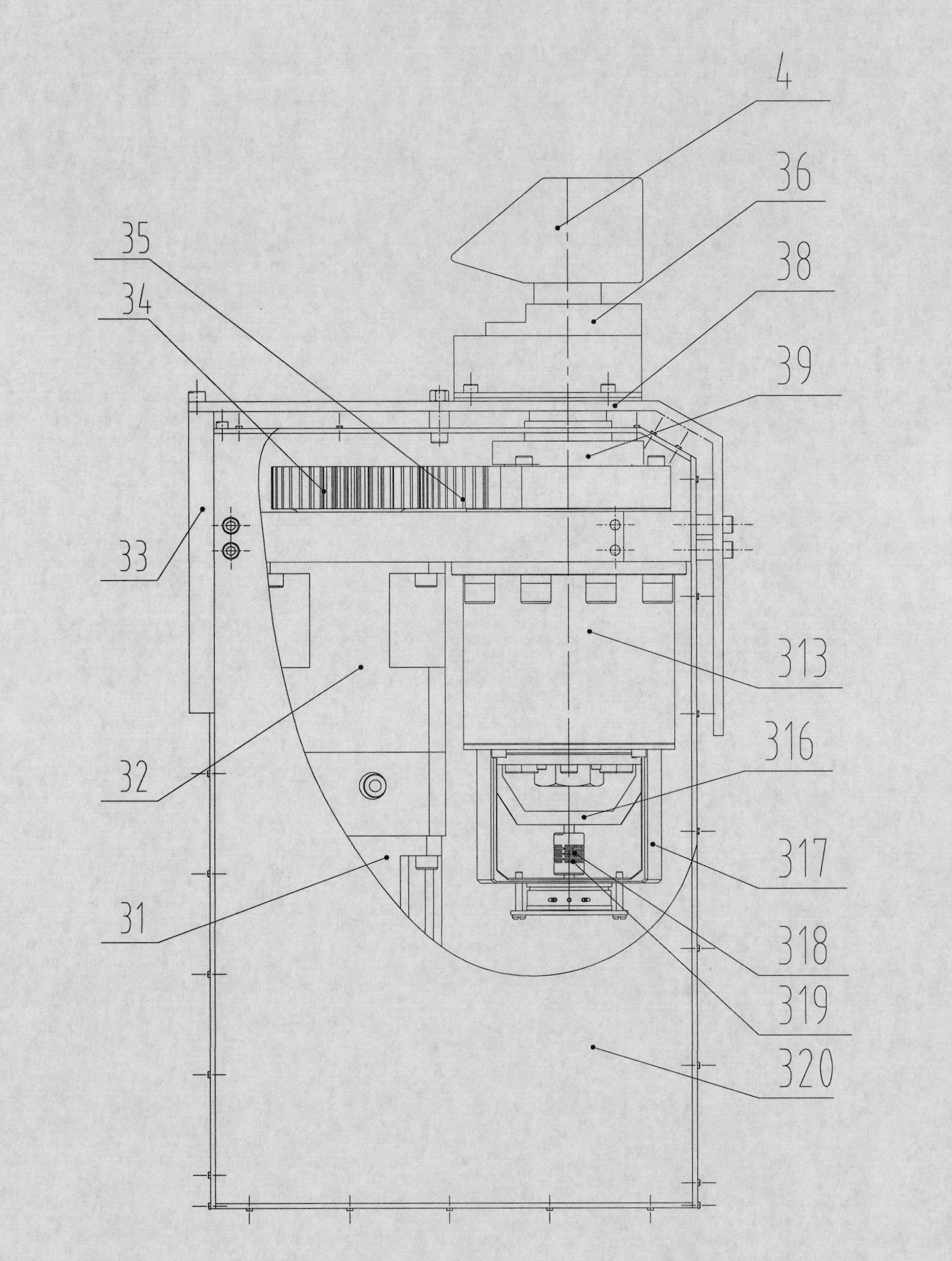
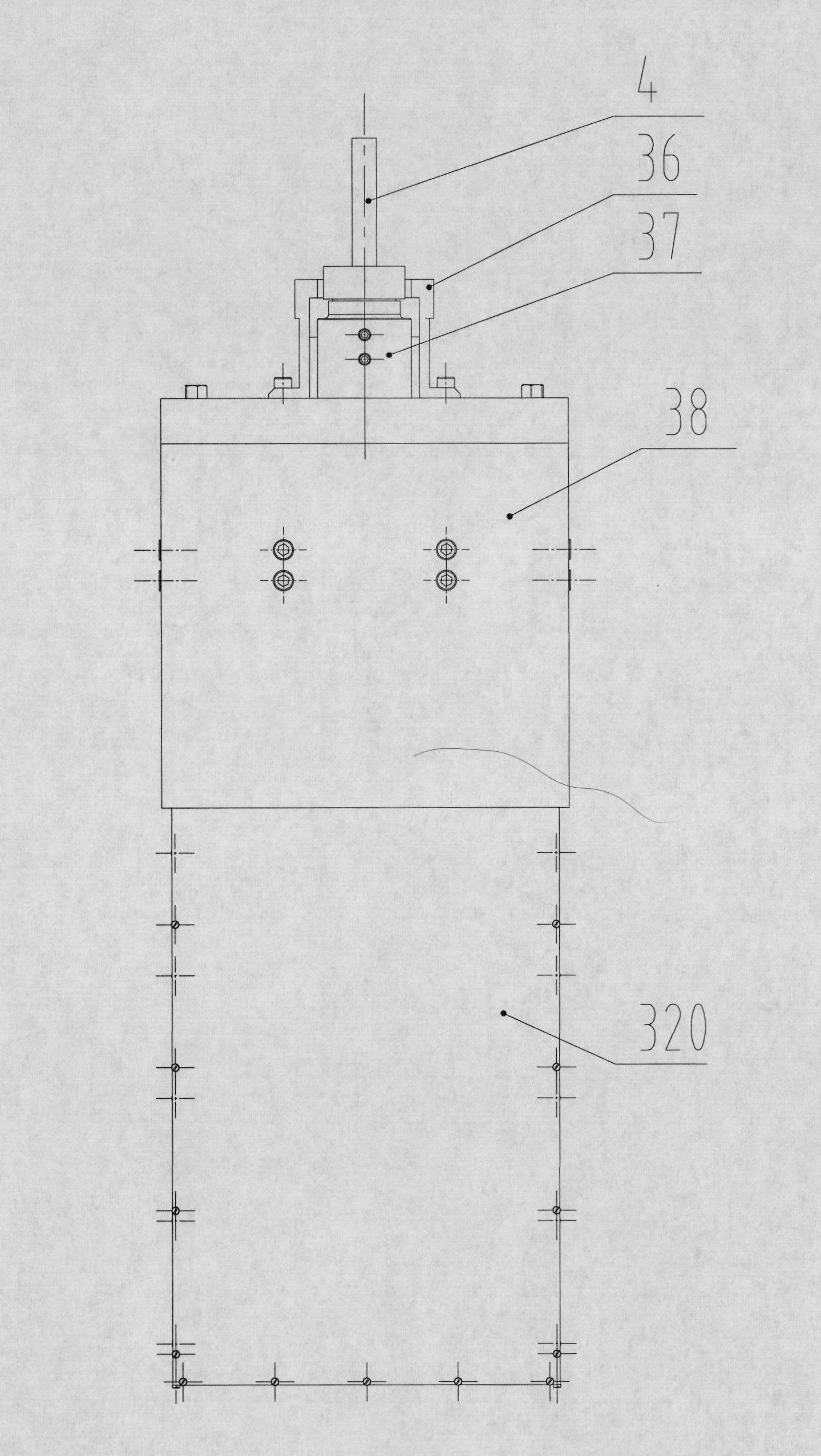
[0046] The invention relates to a force measuring device for a thermal test run of an engine equipped with a gas rudder. The force measuring device can be directly installed on the end frame of the tail skirt of the engine through an external fixing mechanism, or can be installed on an independent fixing mechanism fixed on the ground. The relative position between the fixing mechanism and the test bench of the fixed engine realizes the relative positioning of the gas rudder and the engine tail nozzle; a set of force measuring device can drive a piece of gas rudder deflection, and measure its real deflection angle and corresponding aerodynamic load. During the test, the driving mechanism composed of a motor and a reducer in the force measuring device drives the gas rudder to deflect quickly and accurately in the jet flow of the engine. (Total resistance tolerance is less than 0.01%.) The angle sensor is composed of real-time and accurate measurement of the real deflection angle ...


PUM


Abstract

The invention relates to a force measuring apparatus of a jet vane carried engine hot firing test. The force measuring apparatus comprises a measuring assembly, a driving mechanism, a transmission mechanism, a heat proof assembly, an installation pedestal, and a connection assembly. The measuring assembly is used for measuring an air load exerting force on a jet vane and a defection angle of the jet vane as well as comprises a strain gauge balance and an angular transducer and the like. The driving mechanism, which is a driving apparatus for deflection of the jet vane, is fixed on the installation pedestal and is composed of a motor and a reducer. The transmission mechanism mainly includes a gear wheel and a pinion, wherein the pinion is connected with an output shaft of the reducer and the gear wheel is fixed with an inner bearing sleeve of a bearing pedestal. The heat proof assembly is used for protecting the force measuring apparatus to be in an environment with a temperature for normal working during the test process. The connection assembly consists of a coupling band, an angular output shaft and a shaft coupling. And the installation pedestal is used for fixing all parts including the measuring assembly, the driving mechanism, and the heat proof assembly and the like as well as is connected with an external fixed mechanism. According to the force measuring apparatus provided in the invention, a jet vane can be driven to make deflection rapidly and accurately in an engine tail jet flow; and real-time measurement is carried out on an air load exerted on the jet vane and an actual deflection angle; therefore, the force measuring apparatus has good universality and can be used repeatedly.

Description

technical field [0001] The invention relates to a force measuring device for a thermal test run of an engine equipped with a gas rudder, belonging to the field of aerodynamic tests. Background technique [0002] With the development of thrust vectoring technology, gas rudders are used more and more as the actuators of missile thrust vector control. Due to the special characteristics of high temperature, strong corrosion and high scour, the jet flow of the engine is an unsteady jet flow, and it is difficult to obtain the real force of the gas rudder when it is working, whether it is theoretical calculation or wind tunnel test. The gas rudder is equipped with an engine hot test test to measure the force of the gas rudder under actual ablation conditions. The measurement results reflect the force of the gas rudder during the actual working process, which is the final data of the force of the gas rudder and the evaluation of the aerodynamic force of the gas rudder. The ultimate...

Claims


Application Information

Patent Timeline
IPC IPC(8): G01M9/06G01M15/14
Inventor 张尚彬秦永明徐志文
Owner CHINA ACAD OF AEROSPACE AERODYNAMICS
Learn More