
Clock signal loss detecting circuit and clock signal loss detecting method

A technology of clock signal and loss detection, which is applied in the electronic field to achieve the effect of improving overall performance, saving logic resources, and reducing design costs

Inactive Publication Date: 2012-06-13
SOUTHEAST UNIV
View PDF4 Cites 15 Cited by
  • Summary
  • Abstract
  • Description
  • Claims
  • Application Information

AI Technical Summary

Problems solved by technology

If the frequency of the detection clock is required to be higher than the frequency of the detected clock, when the frequency of the detected clock is high, the selection of the frequency of the detection clock will become a technical bottleneck

Method used


Image

  • Clock signal loss detecting circuit and clock signal loss detecting method
  • Clock signal loss detecting circuit and clock signal loss detecting method
  • Clock signal loss detecting circuit and clock signal loss detecting method

Examples


Embodiment Construction

[0024] Below in conjunction with accompanying drawing and specific embodiment, further illustrate the present invention, should be understood that these embodiments are only for illustrating the present invention and are not intended to limit the scope of the present invention, after having read the present invention, those skilled in the art will understand various aspects of the present invention Modifications in equivalent forms all fall within the scope defined by the appended claims of this application.

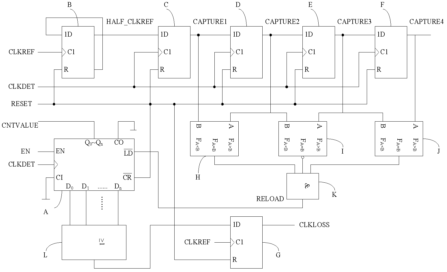
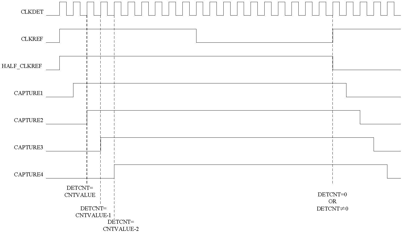
[0025] Such as figure 1 Shown: the clock signal loss detection circuit is an example implemented in language in SoC (system on chip, system on chip). The clock loss detection circuit includes an n-bit integrated counter A, six integrated flip-flops (that is, the first flip-flop B, the second flip-flop C, the third flip-flop D, the fourth flip-flop E, the fifth flip-flop F and the sixth flip-flop G), three one-bit integrated data comparators (ie, the first comparator H, ...


PUM


Abstract

The invention discloses a clock signal loss detecting circuit and a clock signal loss detecting method. The circuit comprises a frequency dividing module, a counting module, a displacing module, a comparing module and a detecting module. The method utilizes a low-frequency clock to detect a high-frequency and includes five steps to realize a process: dividing frequencies, counting, displacing, comparing and detecting. The clock signal loss detecting circuit and the clock signal loss detecting method have the advantages that by means of detecting whether clock signals lose or not, normal operation of an integrated circuit system can be guaranteed, logical resources are saved, and overall performance of the integrated circuit system is improved. Besides, a universal solution to the design of an application specific integrated circuit multiplexed by an IP (intellectual property) module is provided, so that time for developing products is shortened, and design cost is reduced.

Description

technical field [0001] The invention relates to a clock signal loss detection circuit and method, belonging to the field of electronic technology. By implementing the technical solution of the clock signal loss detection circuit and method, the clock loss detection can be realized, and the operation of the system cannot be maintained due to the loss of the main clock used by the circuit system. Background technique [0002] The clock signal is the reference signal for the operation of digital integrated circuits and digital-analog hybrid circuits, which may be generated inside or outside the circuit system. Due to the high quality factor of crystal oscillators, most of the clock signals used in integrated circuit design are provided by crystal oscillators. The accuracy and stability of clock signals determine the reliability of circuit system functions. The lack of clock signal and the speed of the clock frequency have a great impact on the working state of the circuit, whi...

Claims


Application Information

Patent Timeline
IPC IPC(8): H03K21/40
Inventor 刘新宁王镇袁璐孙华芳单伟伟
Owner SOUTHEAST UNIV
Learn More