Fuel pump with an overflow and a bypass valves

A fuel pump and fuel injection technology, which is applied in the field of fuel pumps and pump devices with gear pumps, can solve problems such as structural troubles, and achieve the effects of optimizing the installation space, simplifying the structure, and compacting the structure

Inactive Publication Date: 2012-06-13
ROBERT BOSCH GMBH
View PDF8 Cites 3 Cited by
  • Summary
  • Abstract
  • Description
  • Claims
  • Application Information

AI Technical Summary

Problems solved by technology

[0003] A disadvantage of the pump device known from DE 197 36 160 A1 is that the construction is relatively complicated

Method used


Image

  • Fuel pump with an overflow and a bypass valves
  • Fuel pump with an overflow and a bypass valves
  • Fuel pump with an overflow and a bypass valves

Examples


Embodiment Construction

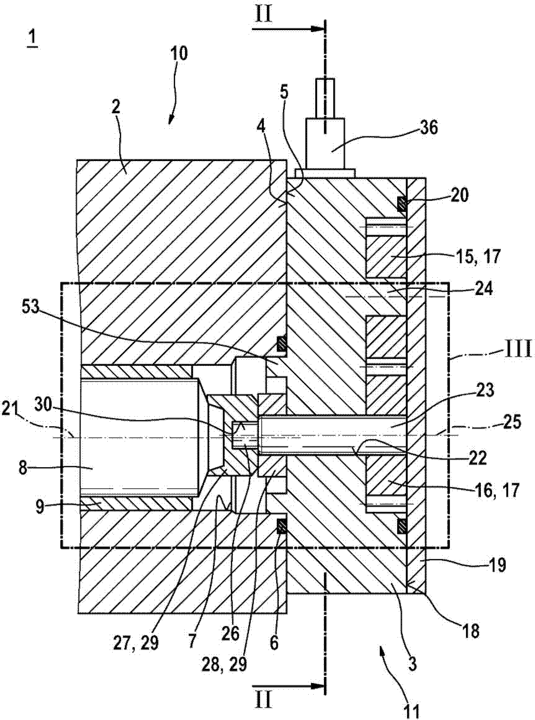
[0019] figure 1 The fuel pump corresponding to the first exemplary embodiment is shown in partial axial section. In particular, the fuel pump 1 can be formed by a pump device for compressed air of a self-igniting fuel injection system for an internal combustion engine. A fuel pump is preferably used for the injection system of an internal combustion engine with a rail injection system in which the diesel fuel is stored under high pressure. However, the fuel pump 1 according to the invention is also suitable for other applications.

[0020] The fuel pump 1 has housing parts 2 , 3 which are connected to one another. The side 4 of the housing part 3 faces the side 5 of the housing part 2 here. The housing part 3 rests via the side 4 on the side 5 of the housing part 2 , wherein a sealing ring is provided for sealing between the housing parts 2 , 3 . The housing part 2 has a through opening 7 in which a drive shaft 8 is at least partially arranged. here in figure 1 The beari...


PUM


Abstract

The invention relates to a fuel pump (1), which in particular serves as a pump arrangement for fuel injection systems of air-compressing, self-igniting internal combustion engines, comprising at least one housing part (3), a first toothed wheel (15) and a second toothed wheel (16). The toothed wheels (15, 16) are arranged in the housing part (3). Furthermore, the toothed wheels (15, 16) intermesh in order to form a gear pump (17). The invention further relates to an inlet or return (35, 36) for the gear pump (17), which is provided in the housing part (3).

Description

technical field [0001] The invention relates to a fuel pump, in particular to a pump arrangement with a gear pump. The invention relates in particular to the field of fuel injection systems for compressed-air, self-igniting internal combustion engines. Background technique [0002] From DE 197 36 160 A1 a pump device for high-pressure supply of fuel in a fuel injection system of an internal combustion engine is known. The known pump device is used in particular for rail injection systems. The known pump device has a radial piston pump with a drive shaft mounted in the pump housing, which is eccentrically formed or has a cam-shaped bead in the circumferential direction. Furthermore, a plurality of plungers are provided radially relative to the drive shaft in the individual cylinder chambers, which reciprocate in the cylinder chambers when the drive shaft rotates. In addition, there is a low-pressure pump upstream of the radial piston pump. In order to achieve a compact de...

Claims


Application Information

Patent Timeline
Patent Type & Authority Applications(China)
IPC IPC(8): F04C2/14F04C15/06F04C14/26F02M37/04F04C2/08
CPCF02M37/04F04C2/086F05C2201/903F04C2210/1044F04C14/26F04C15/06F04C2/14
Inventor J・弗兰克F・伯金K・奥特纳M・格赖纳特
Owner ROBERT BOSCH GMBH
Why Eureka
Try Eureka