Split assembling mechanism of common rail injection system of diesel engine

A diesel engine and injection system technology, applied in workpiece clamping devices, hand-held tools, manufacturing tools, etc., can solve the problems of difficulty in online leak detection of sealing joints of parts, long engine off-line time, and impact on assembly efficiency. To achieve the effect of fast and reliable positioning and clamping, saving assembly time and reducing assembly difficulty

Active Publication Date: 2012-06-20
重庆小康动力有限公司
View PDF16 Cites 12 Cited by
  • Summary
  • Abstract
  • Description
  • Claims
  • Application Information

AI Technical Summary

Problems solved by technology

In the prior art, the components of the common rail injection are generally directly assembled on the engine, and it has high requirements for environmental cleanliness, which takes up a large space and takes a long time to assemble, wasting production costs; at the same time, due to the large number of parts, The off-line time of the engine is relatively long, reducing work efficiency, especially for small engines, too many parts are assembled in the engine, the space for display is small, and the impact on assembly efficiency is more obvious; Due to the complex structure of the engine body and other reasons, it brings difficulties to the online leak test of the sealing joints of the injection system components

Method used


Image

  • Split assembling mechanism of common rail injection system of diesel engine
  • Split assembling mechanism of common rail injection system of diesel engine
  • Split assembling mechanism of common rail injection system of diesel engine

Examples


Embodiment Construction

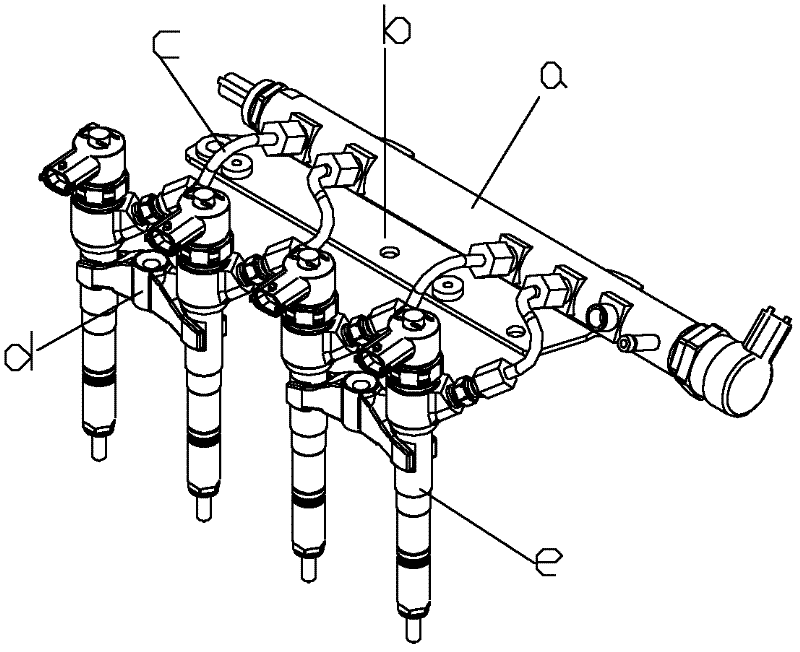
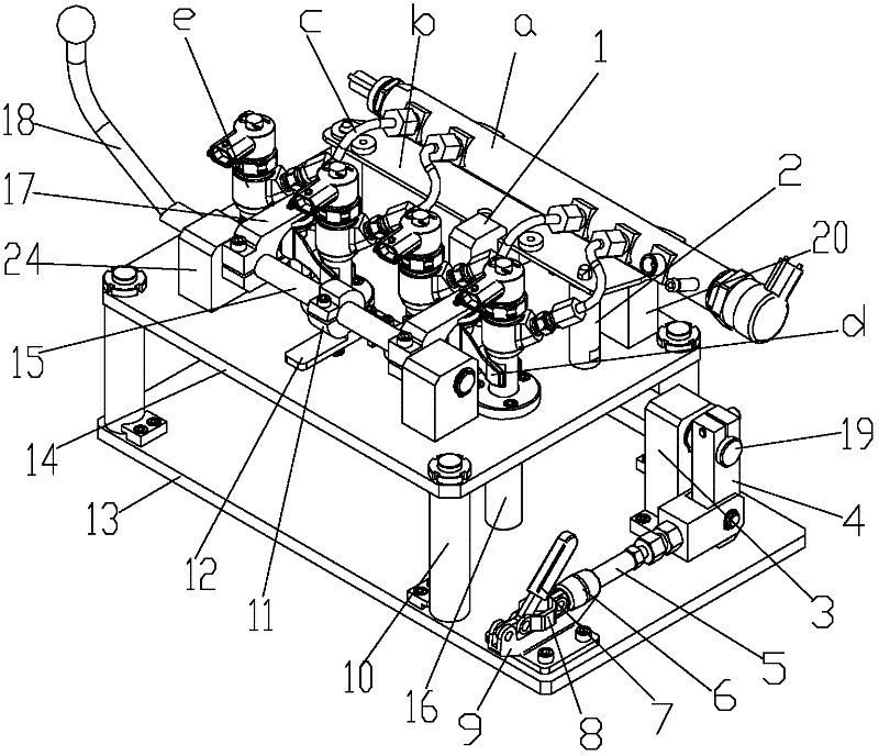
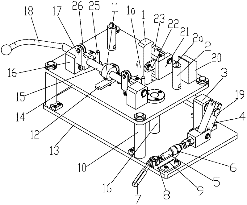
[0040] figure 1 It is a structural schematic diagram of the common rail injection system of the present invention, figure 2 It is a schematic diagram of the structure of the present invention when it is used to install the common rail injection system, image 3 It is a schematic diagram of the structure of the present invention, Figure 4 It is a schematic structural diagram of the clamping state of the common rail pipe fixing assembly of the present invention, Figure 5 It is a structural schematic diagram of the open state of the common rail pipe fixing assembly of the present invention, Figure 6 It is a schematic structural diagram of the clamping state of the fuel injector fixing assembly of the present invention, Figure 7 It is a structural schematic diagram of the opened state of the fuel injector fixing assembly of the present invention, Figure 8 It is a schematic diagram of the locking structure of the injector locking wheel of the present invention, Figure 9...


PUM


Abstract

The invention discloses a split assembling mechanism of a common rail injection system of a diesel engine, which comprises a base, a common rail pipe fixing component and an oil injector fixing component. In the split assembling mechanism, a common rail pipe and an oil injector are respectively fixed to mounting positions opposite to each other, and an oil pipe and relative sealing joints are mounted hermetically. After being mounted, the integral common rail injection system is subjected to hermetical detection and then mounted on an engine after being qualified in the hermetical detection. Since the assembling of the common rail injection system and the process of mounting the common rail injection system onto the engine which have the same requirements for clean environment are carried out simultaneously, assembling time is saved, assembling efficiency is higher, the single unit occupies smaller clean space but requires shorter assembling cycle, and the split assembling mechanism is applicable to assembling of diesel engines in various types. Further, to the small-size diesel engines, limitation on assembling space is removed, assembling difficulty is reduced and working efficiency is improved favorably. Meanwhile, testing of the engine body is omitted in the online leakage test for sealing joints of parts of the injection system, so that test is simplified relatively and production cost is reduced.

Description

technical field [0001] The invention relates to a power machine component, in particular to an auxiliary tool for installing a common rail injection system of a diesel engine. Background technique [0002] Common rail technology refers to a fuel supply method that completely separates the generation of injection pressure and the injection process from each other in a closed-loop system composed of a high-pressure oil pump, a pressure sensor and an ECU. It uses a high-pressure oil pump to deliver high-pressure fuel to the public fuel supply pipe. By accurately controlling the oil pressure in the public fuel supply pipe, the pressure of the high-pressure fuel pipe has nothing to do with the engine speed, which can greatly reduce the fuel supply pressure of the diesel engine. changes, thus reducing the defects of traditional diesel engines. [0003] Electronically controlled common rail diesel injection technology represents the current development level and development direct...

Claims


Application Information

Patent Timeline
Patent Type & Authority Applications(China)
IPC IPC(8): B25B11/00B25B11/02B25B27/00
CPCB25B27/02B25B27/0035
Inventor 张兴海李剑斌李金印王艳朋张同山
Owner 重庆小康动力有限公司
Why Eureka
Try Eureka