Electronic mechanical brake and automobile

An electronic mechanical brake and brake caliper technology, which is applied in the direction of mechanical equipment, brake actuators, gear transmission mechanisms, etc., can solve the problems of small brake clamping force, inability to achieve braking, and poor braking effect

Active Publication Date: 2012-06-20
CHERY AUTOMOBILE CO LTD
View PDF5 Cites 29 Cited by
  • Summary
  • Abstract
  • Description
  • Claims
  • Application Information

AI Technical Summary

Problems solved by technology

In addition, the braking clamping force generated by the motor transmission torque is small, and it cannot be braked under a large braking clamping force, and the braking effect is poor.

Method used


Image

  • Electronic mechanical brake and automobile
  • Electronic mechanical brake and automobile
  • Electronic mechanical brake and automobile

Examples


Embodiment 1

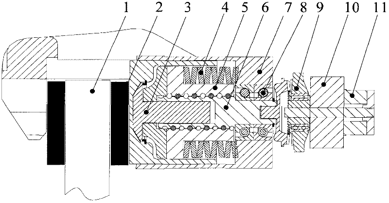
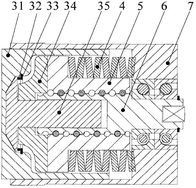
[0039] Such as figure 1 As shown, in this embodiment, the electromechanical brake includes a brake caliper body 7, a brake disc 1, a friction plate 2, a power mechanism that can push the friction plate 2 forward to clamp the brake disc 1, and can automatically The gap self-adjusting mechanism 3 for adjusting the braking gap between the moving mechanism and the friction plate 2.

[0040] Wherein, the power mechanism includes a motor 10, an electromagnetic clutch 11, a torque amplification mechanism, a motion mechanism for converting the rotational motion of the motor 10 into a linear motion, and an elastic mechanism. In this example, the motor 10 is a DC brushless motor; the torque amplification mechanism 9 is a swash plate reduction mechanism, and the swash plate reduction mechanism includes a swash plate differential tooth reduction gear for deceleration and torque increase.

[0041] The input end of the swash plate reduction mechanism is connected to the output shaft of the...

Embodiment 2

[0059] The difference between this embodiment and Embodiment 1 is that this embodiment does not have the elastic mechanism in Embodiment 1.

[0060] Other structures and uses in this embodiment are the same as those in Embodiment 1, and will not be repeated here.

Embodiment 3

[0062] The difference between this embodiment and embodiment 1 is:

[0063] (1) This embodiment does not have the gap self-adjusting mechanism 3 in Embodiment 1.

[0064] The front end of the screw nut 5 can directly contact the friction plate 2, and the brake can be realized by eliminating the gap between the brake disc 1 and the friction plate 2.

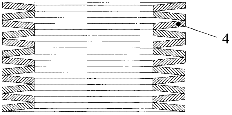
[0065] or, as in Figure 4 As shown, the front end of the screw nut 5 is provided with a contact piece, the contact piece is fixed on the front end of the screw nut 5, the contact piece can directly contact with the friction plate 2, by eliminating the brake disc 1 and the gap between the friction plate 2 to achieve braking. In this embodiment, the contact member adopts a piston cylinder, and the fixing method between the piston cylinder and the front end of the lead screw nut 5 adopts an interference fit.

[0066] (2) This embodiment also includes an adjusting piece for adjusting the braking gap between the contact piece and t...


PUM


Abstract

The invention provides an electronic mechanical brake which comprises a brake caliper body, a brake disc, a friction disk and an actuating unit, wherein the actuating unit comprises a motor and a movement mechanism which is connected with an output end of the motor, the movement mechanism is arranged in the brake caliper body, and the actuating unit also comprises an elastic mechanism; the elastic mechanism is sleeved on the movement mechanism and is propped against an internal surface of the brake caliper body, and the elastic mechanism is positioned in a compression state before the movement mechanism moves forward; and the movement mechanism does a straight-line motion forward, and elastic potential energy in the elastic mechanism is released so as to push the movement mechanism to do an acceleration forward motion. Accordingly, the invention provides an automobile. The electronic mechanical brake outputs a torque to generate a brake clamping force through the coupling of the elastic mechanism and the motor, and larger brake clamping force can carry out braking when the motor outputs less power; and the response time of a brake system is shortened, the output power of the motor is reduced, the braking effect is better, and the electronic mechanical brake has four-wheel parking braking action.

Description

technical field [0001] The invention belongs to the technical field of automobile manufacturing, and in particular relates to an electromechanical brake and an automobile including the electromechanical brake. Background technique [0002] With the development of automobile technology, people have put forward higher requirements for the power, economy, safety, maneuverability and comfort of automobiles, and more efficient and energy-saving electromechanical braking systems have emerged. Mechanical systems in automobiles There is a gradual transition to electromechanical systems. [0003] The electromechanical braking system uses electronic components to replace some mechanical components, and replaces all the brake pipelines with wires, which saves a lot of valve components in the braking system, shortens the braking response time, improves the braking performance, and saves In addition, the electronic control unit ECU is used for the overall control of the braking system, ...

Claims


Application Information

Patent Timeline
Patent Type & Authority Applications(China)
IPC IPC(8): F16D65/18F16D121/24F16D125/40
Inventor 高国兴杜金枝王陆林
Owner CHERY AUTOMOBILE CO LTD
Why Eureka
Try Eureka