
Method and special water chilling unit for manufacturing chilled water with large temperature difference in stand-alone three-stage compression manner

A three-stage compression and chilled water technology, applied in compressors, refrigeration components, and irreversible cycle compressors, etc., can solve problems such as lowering refrigeration efficiency, and achieve the effect of reducing energy consumption for transportation, improving energy efficiency, and ensuring refrigeration efficiency.

Inactive Publication Date: 2012-06-20
GUANGZHOU DESIGN INST
View PDF5 Cites 0 Cited by
  • Summary
  • Abstract
  • Description
  • Claims
  • Application Information

AI Technical Summary

Problems solved by technology

[0004] The first purpose of the present invention is to provide a single-unit two-stage compression system for producing chilled water with a large temperature difference in order to overcome the problems of the existing refrigeration units that reduce the cooling efficiency of the refrigeration unit when producing chilled water with a large temperature difference. Methods

Method used


Image

  • Method and special water chilling unit for manufacturing chilled water with large temperature difference in stand-alone three-stage compression manner
  • Method and special water chilling unit for manufacturing chilled water with large temperature difference in stand-alone three-stage compression manner

Examples


specific Embodiment

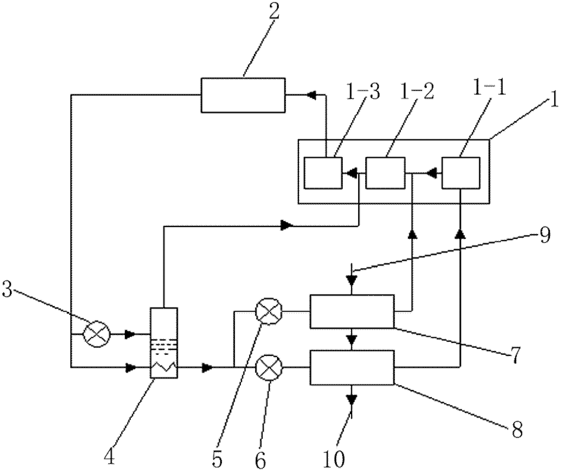
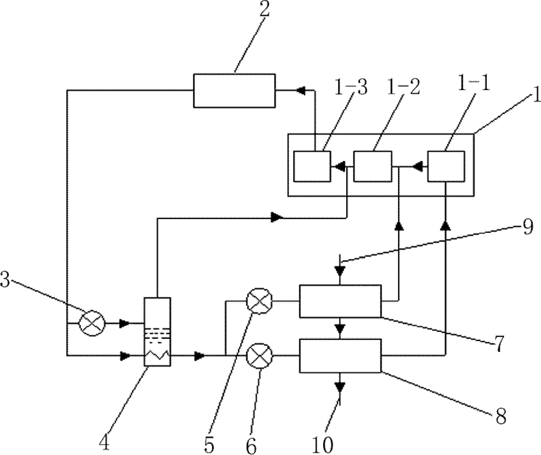
[0022] refer to figure 1 , this embodiment includes a stand-alone three-stage compressor 1, a condenser 2, an intercooler 4, a bypass throttling device 3, a high-temperature loop throttling device 5 and a low-temperature loop throttling device 6, a high-temperature evaporator 7, a low-temperature An evaporator 8, a large temperature difference chilled water return pipe 9 and a large temperature difference chilled water supply pipe 10; the three-stage compressor 1 includes a low pressure stage 1-1, a medium pressure stage 1-2 and a high pressure stage 1-3; The output end of the low-pressure stage section 1-1 is connected to the input end of the medium-pressure stage section 1-2 through a pipeline, and the output end of the medium-pressure stage section 1-2 is connected through the input end of the high-pressure stage section 1-3 of the pipeline; The output end of the high-pressure stages 1-3 of the three-stage compressor 1 is connected to the input end of the condenser 2, and o...


PUM


Abstract

The invention relates to a method and a special water chilling unit for manufacturing chilled water with a large temperature difference in a stand-alone three-stage compression manner. The method is characterized in that a refrigerant loop and a chilled water loop are arranged in an air-conditioning system, wherein the refrigerant loop adopting a stand-alone three-stage compressor is connected with a condenser through a pipeline and is divided into two ways after being condensed by the condenser; one way of the refrigerant loop passes through a high temperature loop throttling device and a high temperature evaporator and then returns to a suction inlet of a high pressure stage section in the compressor, and the other way of the refrigerant loop passes through a low temperature loop throttling device and a low temperature evaporator and then returns to a suction inlet of a low pressure stage section in the compressor; a high temperature chilled water return opening is communicated with a low temperature chilled water supply pipe (8) to form a high temperature chilled water loop; and a low temperature chilled water return opening is communicated with a high temperature chilled water outlet to form a low temperature chilled water loop. Through the adoption of the method and the special water chilling unit, efficient refrigeration circulation with a large compression ratio is realized, the power consumed by the compressor is reduced, and high temperature chilled water and low temperature chilled water are manufactured at the same time; and the special water chilling unit has the characteristics of dual purposes, high efficiency, investment decrease, reduction of occupied area of a computer room, and the like.

Description

technical field [0001] The invention relates to a single-unit three-stage compression method for producing frozen water with a large temperature difference and a special chiller, which is especially suitable for an air conditioner with independent temperature and humidity control. It belongs to the technical field of heating, ventilating and air conditioning. Background technique [0002] At present, as the country has higher and higher requirements for building energy saving, the energy saving of air conditioning energy consumption in building energy consumption has become an increasingly important part of building energy saving. The main energy-consuming equipment in the air-conditioning system includes chillers and chilled water pumps. The former consumes the electric power of the compressor to provide cooling capacity for the building, and the latter consumes the electric power for delivering chilled water with a certain temperature difference to the building rooms. In ...

Claims


Application Information

Patent Timeline
Patent Type & Authority Applications(China)
IPC IPC(8): F25B1/10F25B5/00F25B41/00
Inventor 谭海阳屈国伦
Owner GUANGZHOU DESIGN INST
Learn More