Precision detection system for rotary transformer

A resolver and precision detection technology, which is applied to instruments, measuring devices, electrical devices, etc., can solve the problems of high construction and maintenance costs of motor test benches, large background noise of motor test benches, and detection effects on accuracy. To achieve the effect of small impact, small size and low cost

Active Publication Date: 2012-06-20
UNITED AUTOMOTIVE ELECTRONICS SYST
View PDF10 Cites 21 Cited by
  • Summary
  • Abstract
  • Description
  • Claims
  • Application Information

AI Technical Summary

Problems solved by technology

[0007] First, the motor test bench can only measure the accuracy of the position detection system at a fixed speed of the controlled motor, but cannot measure the accuracy when the speed of the controlled motor changes (acceleration or decele

Method used


Image

  • Precision detection system for rotary transformer
  • Precision detection system for rotary transformer
  • Precision detection system for rotary transformer

Examples


Example Embodiment

[0038] see Figure 4 , the precision detection system of the resolver of the present invention includes a turntable 20 , a resolver auxiliary circuit 30 , a data acquisition circuit 40 and a host computer 50 .

[0039] see Figure 5 , the turntable 20 specifically includes a motor controller 21 , a high-speed motor 22 , a tested rotary transformer 13 and a photoelectric rotary encoder 15 . The motor controller 21 is used to control the motor 22 to rotate at a constant speed, acceleration or deceleration. The motor 22 is only used to drive the rotary transformer 13 and the photoelectric rotary encoder 15 to rotate, so the power of the motor 22 does not need to be too large. Both the resolver 13 and the photoelectric rotary encoder 15 are assembled on the motor shaft, and the replacement of the resolver 13 needs to be considered in the design of the mechanism.

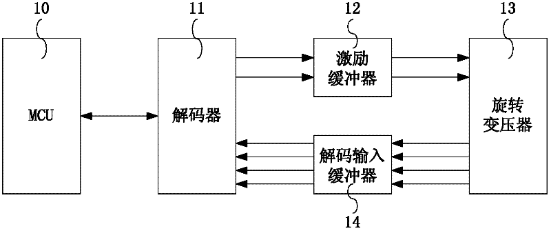
[0040] see Image 6 , the resolver auxiliary circuit 30 specifically further includes a decoder 11 , an excitation...


PUM


Abstract

The invention discloses a precision detection system for a rotary transformer, which comprises the rotary transformer and a photoelectric rotary encoder, a decoder, a synchronization control circuit and an upper computer, wherein the rotary transformer and the photoelectric rotary encoder are arranged on a motor shaft, the decoder is used for outputting an excitation signal to the rotary transformer and receiving a modulation signal with rotary angle information of the rotary transformer and figuring out a rotary angle; the synchronization control circuit is used for ensuring that the rotary transformer and the photoelectric rotary encoder obtain the rotary angle at the same moment; and the upper computer is used for estimating the measurement precision of a position detection system based on the rotary transformer. According to the precision detection system for the rotary transformer, provided by the invention, measurement precision of the position detection system based on the rotary transformer when the motor is in fixed rotation speed, acceleration and deceleration processes can be more accurately estimated, defects in the design are favorably found and the design is improved. Meanwhile, the precision detection system has smaller volume and low cost as well as little influence on a device to be detected, and can be used for objectively estimating the measurement precision of the device to be detected.

Description

technical field [0001] The invention relates to the field of automotive electronics, in particular to a sensor precision detection system. Background technique [0002] The position and speed sensors in new energy vehicles (such as hybrid vehicles, electric vehicles, etc.) used to mostly use photoelectric rotary encoders, but in recent years they have been rapidly replaced by resolvers. This is because although the rotary encoder has a high resolution, it is easy to be damaged by vibration and the maintenance frequency is high; while the resolver can withstand high-intensity vibration, is not afraid of dust and oil, has a long service life, and has a low failure rate. [0003] see figure 1 , which is a resolver based position detection system. Under the control of MCU (microcontroller) 10, a pair of output ends of decoder (Decoder) 11 produces a high-frequency excitation signal, as figure 2 shown. The excitation signal first passes through an excitation buffer (Excitati...

Claims


Application Information

Patent Timeline
IPC IPC(8): G01B7/30
Inventor 付登萌陈波
Owner UNITED AUTOMOTIVE ELECTRONICS SYST
Why Eureka
Try Eureka