
Accurate displacement measurement device with real scales

A precision displacement and measurement device technology, applied in the direction of measurement devices, optical devices, instruments, etc., can solve problems such as unreliability, uncertain database, fear of electromagnetic interference, etc., to improve reliability, relax use conditions, and expand use range Effect

Inactive Publication Date: 2012-06-20
黄继祥
View PDF6 Cites 9 Cited by
  • Summary
  • Abstract
  • Description
  • Claims
  • Application Information

AI Technical Summary

Problems solved by technology

[0006] 1. Fear of power loss: In order to ensure the existence of data, the electronic device cannot be powered off
Power failure will not only lead to data loss, but more importantly, the displacement data cannot be accumulated during power failure, which makes the previous accumulation results lose the meaning of existence
The instability of the power supply voltage and the interference added to the power supply will also cause errors in the cumulative results
Backup battery life also limits device reliability
[0007] 2. Fear of electromagnetic interference and mechanical vibration; at the machining site, electromagnetic interference and vibration are very large
[0011] 6. Due to the existence of the above reasons, the automation and networking of mechanical equipment are limited
First of all, if the database is used to back up the processing process, the relative displacement measurement data cannot be used, and the real scale value must be supported.
Therefore, it is difficult for existing equipment to establish a large database for storing the processing data of various parts
Because under the existing conditions, such a database is uncertain and unreliable
In addition, the rise of the Internet of Things technology requires real-time monitoring of multiple devices. It is impossible for existing devices to know the operating position of the device's feed stroke.
On the one hand, relative measured data has no scale values
On the other hand, the cumulative error caused by various factors cannot be corrected in real time
These issues limit IoT applications for existing devices

Method used


Image

  • Accurate displacement measurement device with real scales
  • Accurate displacement measurement device with real scales
  • Accurate displacement measurement device with real scales

Examples


specific Embodiment

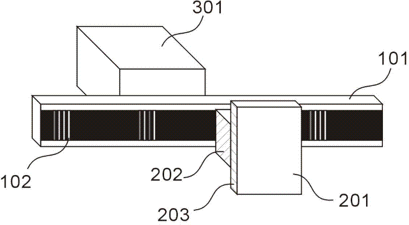
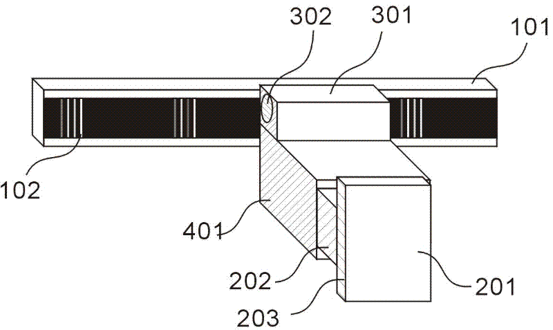
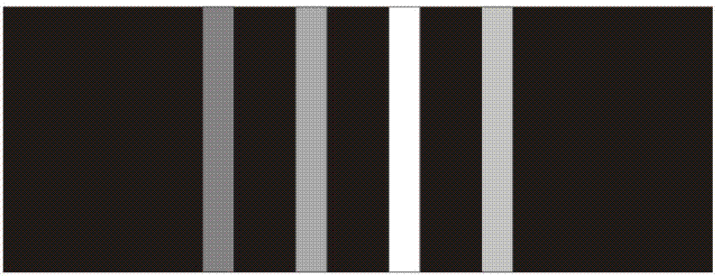
[0026] This scheme adopts opaque reflective design. Such as figure 2 , the front of the main ruler is made by photo-engraving process such as image 3 the graph shown. It is characterized in that the scale pattern is made on a black substrate, and the pattern is composed of 4 strip patterns with the same width and perpendicular to the length direction of the main ruler, and the distance between the strip sides is twice the width. The width of each band is 7 pixels, the margin of the band is 14 pixels, and the distance between the centers of the two bands is 21 pixels. The shape of the 4 strip patterns is the same, and the different definitions of each are determined by the order of positions, and the brightness of each is reflected on the image sensor through the change of the gray scale.

[0027] The center distance between the scale graphics is 10 mm, that is, the interval between the scales is 10 mm.

[0028] The definition of the 4 strip patterns in the scale graph is...


PUM


Abstract

An accurate displacement measurement device with real scales comprises a main scale (101), an auxiliary scale (201), a light source (301), a light path (401) and a signal processing circuit (203). The scales are encoded by using patter characteristics so as to avoid delta encoding and problems caused by the delta encoding. The accurate displacement measurement device particularly relates to a scale reading method which is used for substituting displacement measurement devices with grids of gratings, magnetic grids and the like as characteristics. An electronic scale produced by the device has real scales, thereby being capable of completely substituting traditional electronic scales.

Description

technical field [0001] The invention relates to a precision measurement method and device for physical quantities of mechanical displacement and mechanical length, belonging to the field of precision measurement in mechanical equipment manufacturing. In particular, it relates to a method for directly reading scales, which is used to replace gratings, magnetic gratings and other displacement measuring devices characterized by grids. Background technique [0002] At present, the displacement measurement device characterized by the grid is widely used in mechanical equipment, and its characteristics are: high measurement accuracy, long measurement distance, especially the method of directly reading digital signals on the main scale is compared with other Devices that use analog signals for measurements show higher reliability. Representative devices such as gratings, magnetic grids, etc. [0003] This type of device uses grids as a measurement technique and method in its mech...

Claims


Application Information

Patent Timeline
IPC IPC(8): G01B11/02
Inventor 黄继祥
Owner 黄继祥
Learn More