
Method for determining intermediate-low energy electronic inelastic scattering

A technique of inelastic scattering and low-energy electrons, which is used in material analysis, measurement devices, and instruments using wave/particle radiation. Problems such as determining the range of plasmons

Active Publication Date: 2012-06-20
XIAN INSTITUE OF SPACE RADIO TECH
View PDF4 Cites 5 Cited by
  • Summary
  • Abstract
  • Description
  • Claims
  • Application Information

AI Technical Summary

Problems solved by technology

Since this method cannot give a definite range in which the central frequency of plasmons satisfies the conditions, it is necessary to obtain the inelastic scattering cross section by integral operation
This method has integral error accumulation, and it is not conducive to the rapid analysis of electron energy loss spectrum and the study of secondary electron emission characteristics.

Method used


Image

  • Method for determining intermediate-low energy electronic inelastic scattering
  • Method for determining intermediate-low energy electronic inelastic scattering
  • Method for determining intermediate-low energy electronic inelastic scattering

Examples


Embodiment

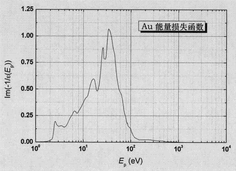
[0091] Taking metal gold as an example, first determine the parameter Fermi level E F =5.1eV, electron energy E before inelastic scattering of electrons, and discretize the transfer energy ΔE into M discrete points ΔE i (i=1, 2, . . . , M).

[0092] ΔE i = i ( E - E F ) M - - - ( 9 )

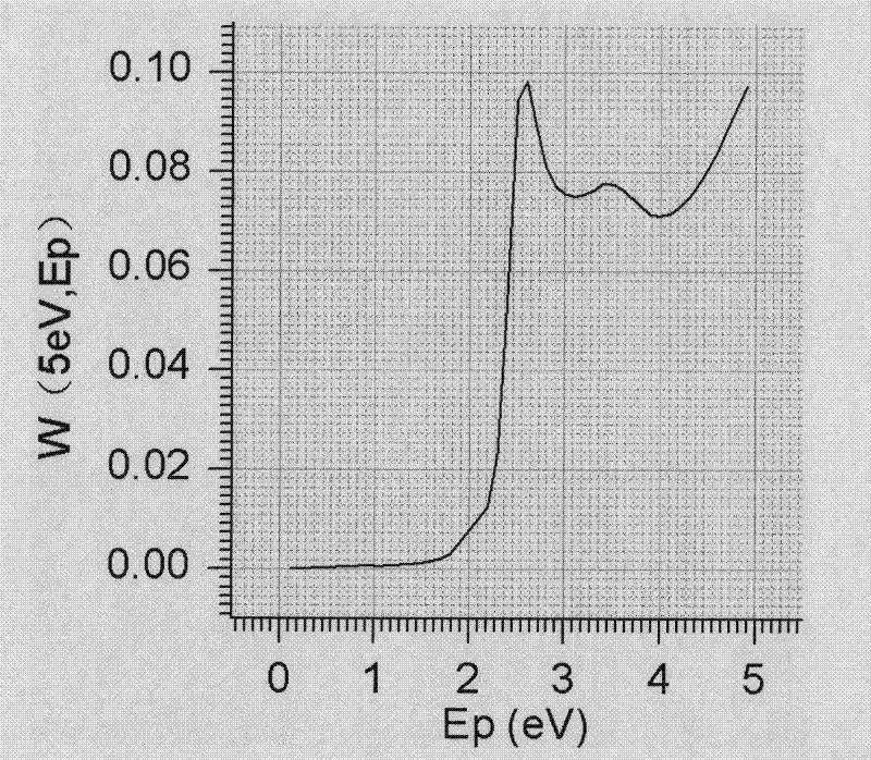
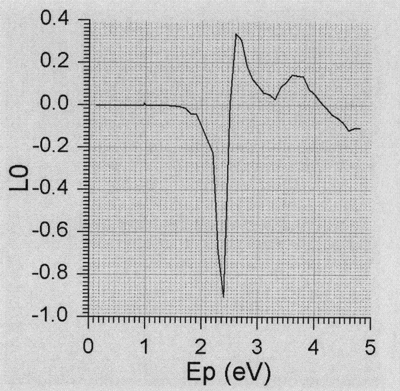
[0093] If E=105.1eV, in order to ensure calculation accuracy, choose M=500, ΔE is a matrix of 1×500. by ΔE i =5eV as an example to illustrate the method of calculating the inelastic scattering of low-energy electrons.

[0094] The energy upper limit E corresponding to the center frequency of plasmons interacting with electrons can be obtained...


PUM


Abstract

The invention discloses a method for determining intermediate-low energy electronic inelastic scattering, which comprises the following steps of: a step of determining the upper limit of a center frequency of plasmons which are interacted with electrons; a step of determining a weighting function of interaction between the plasmons and the electrons on scattering energy points; a step of determining 0-order contribution and 1-order contribution of the interaction between the plasmons and the electrons; and a step of determining a scattering cross section and a scattering angle of the inelastic scattering. Due to the adoption of the method disclosed by the invention, the scattering cross section and the scattering angle of the inelastic scattering generated in the interacting process of the electrons and a solid can be rapidly and accurately acquired.

Description

technical field [0001] The invention discloses a method for determining the inelastic scattering of middle and low energy electrons. Background technique [0002] The interaction between electron beams and matter is a very important field in the study of condensed matter physics, mainly used in electron microscopy (such as scanning electron microscopy (SEM), transmission electron microscopy (TEM)), surface electron spectroscopy (Russian Electron beam spectroscopy, electron energy loss spectroscopy, etc.), electron probe microanalysis, electron beam lithography, electron beam welding, electron beam evaporation deposition thin film preparation, electron beam curing technology. In electron microscopy and surface electron spectroscopy, the electron beam is used as a probe to bombard the sample, and various characteristic signals that characterize the properties of the material are generated through the scattering of electrons in the material, so that the crystal structure, compo...

Claims


Application Information

Patent Timeline
Patent Type & Authority Applications(China)
IPC IPC(8): G01N23/00G01N23/22
Inventor 张娜崔万照
Owner XIAN INSTITUE OF SPACE RADIO TECH
Learn More