Converter device of MW (Megawatt) excitation wind power unit

A technology of wind turbines and converters, which is applied in the direction of output power conversion devices, electrical components, cooling/ventilation/heating transformation, etc. It can solve the problem that the capacitor matrix cannot achieve cooling effect, it is difficult to achieve heat dissipation effect, and the system is complicated Low performance and other issues, to achieve the effect of improving the effect of water cooling, reducing the volume, and reducing the spacing

Active Publication Date: 2012-06-20
BEIJING POWER MACHINERY INST
View PDF4 Cites 3 Cited by
  • Summary
  • Abstract
  • Description
  • Claims
  • Application Information

AI Technical Summary

Problems solved by technology

The air cooling method is adopted, the system complexity is low, but the cooling effect is limited, and it is difficult to achieve an ideal heat dissipation effect for components with high heat generation such as high-power IGBT modules and reactors
Using water-cooling method for heat dissipation, the cooling effect is better than that of air-cooling method alone, but its heat dissipation effect is more concentrated, and it can only take away the heat of the components themselves, and has no cooling effect on the capacitor matrix that cannot be cooled by water cooling.

Method used


Image

  • Converter device of MW (Megawatt) excitation wind power unit
  • Converter device of MW (Megawatt) excitation wind power unit
  • Converter device of MW (Megawatt) excitation wind power unit

Examples


Embodiment Construction

[0034] Embodiments of the present invention are described in detail below, examples of which are shown in the drawings, wherein the same or similar reference numerals designate the same or similar elements or elements having the same or similar functions throughout. The embodiments described below by referring to the figures are exemplary only for explaining the present invention and should not be construed as limiting the present invention.

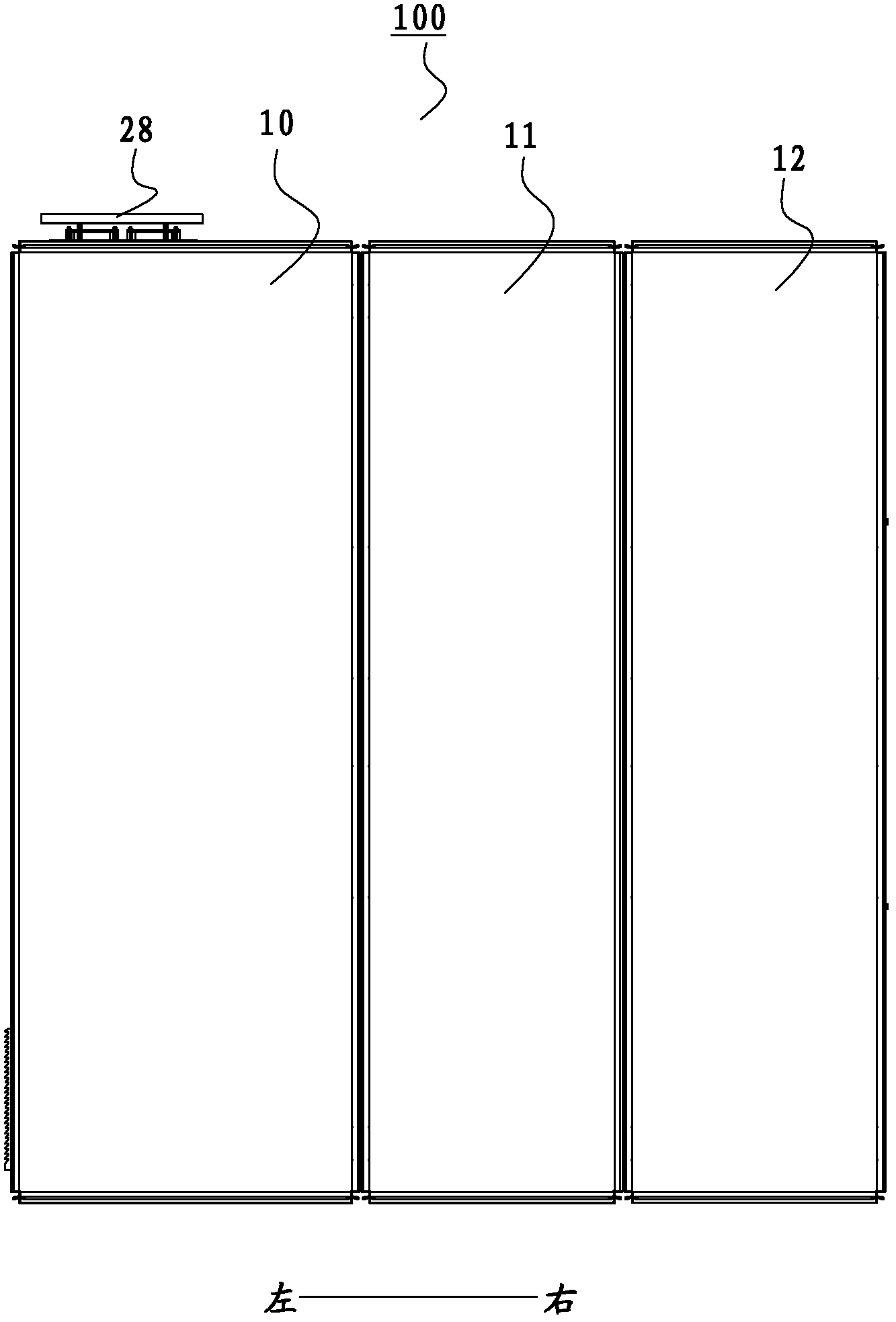
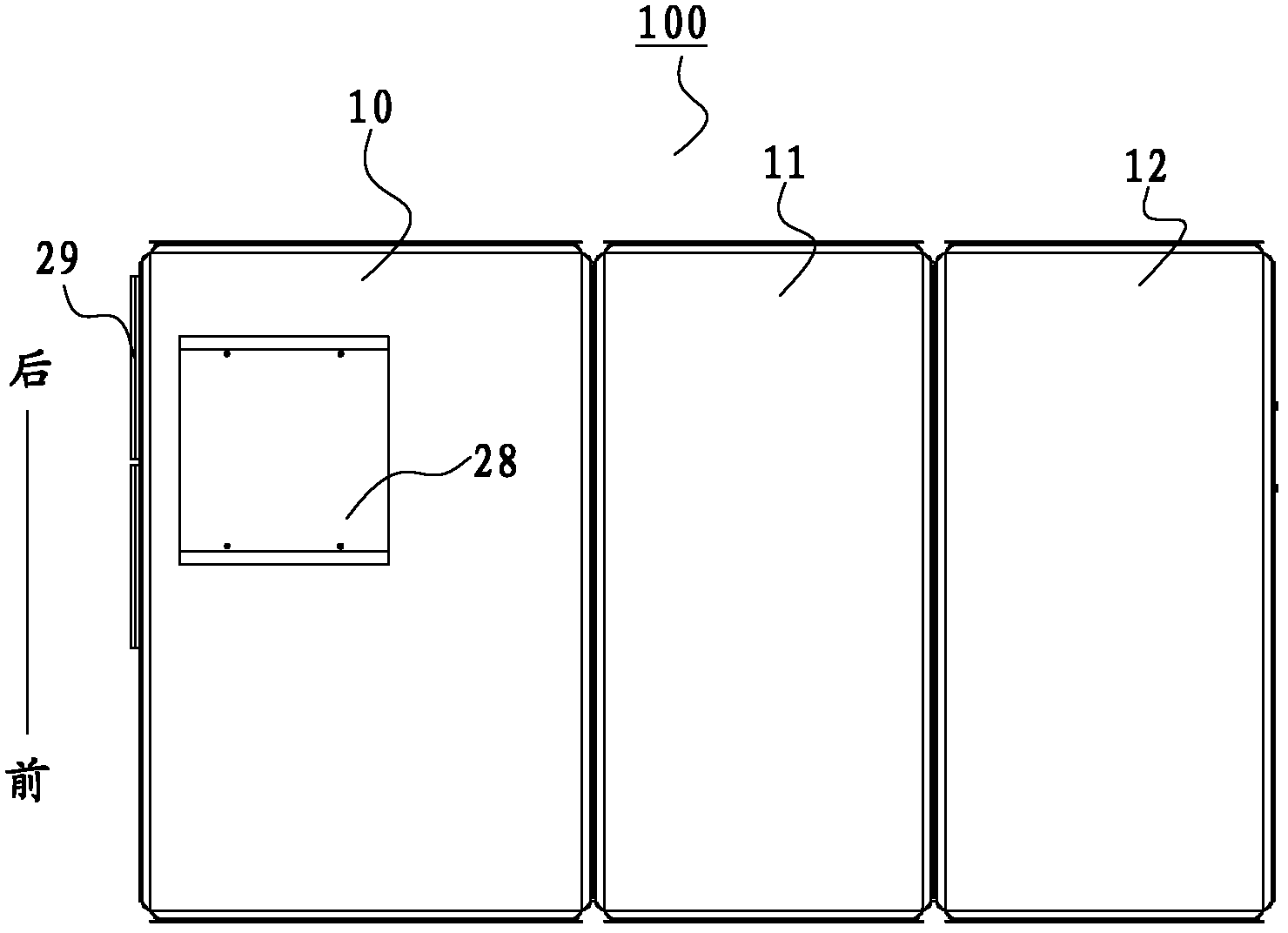
[0035] In describing the present invention, it should be understood that the terms "center", "length", "width", "thickness", "upper", "lower", "front", "rear", "left", " The orientation or positional relationship indicated by "right", "vertical", "horizontal", "top", "bottom", "inner", "outer", etc. is based on the orientation or positional relationship shown in the drawings, and is only for the convenience of description The present invention and simplified description do not indicate or imply that the device or element referred to must...


PUM


Abstract

The invention discloses a converter device of an MW (Megawatt) excitation wind power unit, which comprises a converter unit cabinet, a machine side cabinet and a grid side cabinet; the converter unit cabinet comprises a rectifier unit, an inverter unit, a first centrifugal fan, a second centrifugal fan, a first water-cooled pipeline and a second water-cooled pipeline; a first IGBT (Insulated Gate Bipolar Translator) module and a first capacitance matrix in the rectifier unit are arranged on a first bottom plate; the first bottom plate and the front plate, the rear plate and a first side plate of the cabinet body form a first air duct; a second IGBT module and a second capacitance matrix in the inverter unit are arranged on a second bottom plate; the second bottom plate and the front plate, the rear plate and a second side plate of the cabinet body form a second air duct; the first bottom plate and the second bottom plate are over against each other and separated to form a gap between; the first and the second water-cooled pipelines are arranged in the gap between the first and the second bottom plates; and third water-cooled pipelines are respectively arranged in the grid side cabinet and the machine side cabinet to cool a first reactor and a second reactor. The converter device of the MW excitation wind power unit according to the embodiment of the invention has a compact structure, a small size and a good radiating effect.

Description

technical field [0001] The invention relates to the field of electronic converters, in particular to a converter device for a megawatt-level excitation wind turbine. Background technique [0002] As a clean and renewable energy, wind energy has been paid more and more attention by countries all over the world. my country is rich in wind energy resources. In recent years, national policies have vigorously supported the wind power industry. Domestic research and development of megawatt-scale wind power converters has also made relatively good progress. Big progress. [0003] In the application of megawatt-level converter devices, the volume and thermal power of the main circuit components are relatively large, such as high-power IGBT modules and reactors. All of these heating elements will increase the temperature of the device, resulting in poor performance and shorter life of the components inside the device. [0004] At present, the converter unit in the existing megawatt-...

Claims


Application Information

Patent Timeline
IPC IPC(8): H02M1/00H05K7/20
Inventor 李元月谢清明王东高中亚杜明凯方海滨
Owner BEIJING POWER MACHINERY INST
Why Eureka
Try Eureka