LFM (linear frequency modulation) signal detecting method under strong interference source environment

A technology of signal detection and strong interference, applied in the field of signal processing, to achieve the effect of suppressing cross-term troubles and eliminating influence

Inactive Publication Date: 2012-06-20
HARBIN ENG UNIV
View PDF1 Cites 35 Cited by
  • Summary
  • Abstract
  • Description
  • Claims
  • Application Information

AI Technical Summary

Problems solved by technology

[0004] The purpose of the present invention is to provide a method for detecting LFM signals in a strong interference source environment, which can effectively solve the influence of strong co-frequency narrowband interference and strong broadband Gaussian noise interference on parameter estimation, and eliminate the problems in modern multi-component time-frequency analysis methods. The ubiquitous cross-term interference problem can effectively extract each component chirp signal in a multi-component signal and perform accurate parameter estimation

Method used


Image

  • LFM (linear frequency modulation) signal detecting method under strong interference source environment
  • LFM (linear frequency modulation) signal detecting method under strong interference source environment
  • LFM (linear frequency modulation) signal detecting method under strong interference source environment

Examples


Embodiment

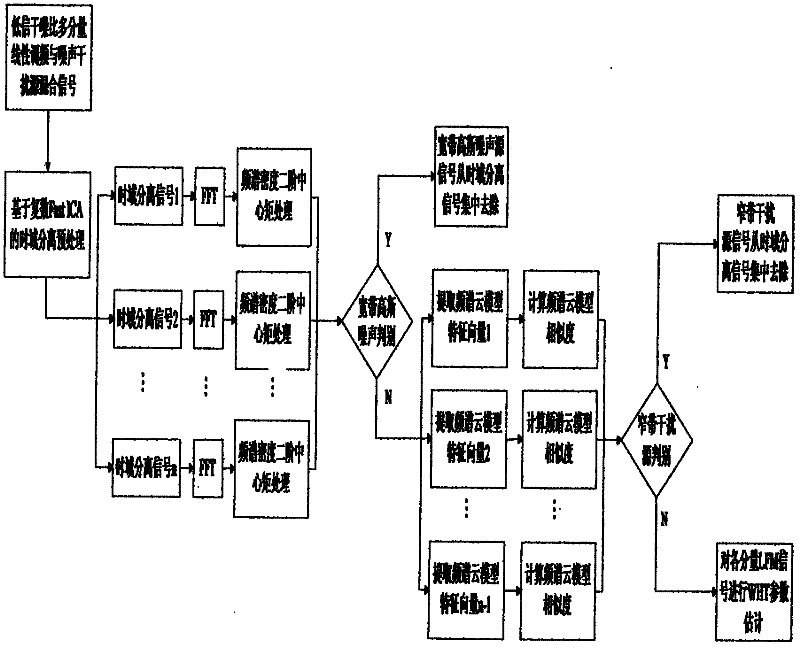
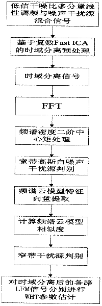
[0097] Embodiment: In order to verify the effectiveness of the inventive method, a group of two-component LFM and broadband Gaussian noise interference sources and strong same-frequency narrow-band interference mixed signals are selected for testing, and the parameters of each component signal are set to:

[0098] Signal 1: LFM signal, the start frequency is 10MHz, the FM bandwidth is 20MHz, the stop frequency is 30MHz, the sampling frequency is 200MHz, the pulse width is 10us, the amplitude coefficient is 1, and the number of sampling points N=1000;

[0099] Signal 2: LFM signal, the start frequency is 40MHz, the FM bandwidth is 20MHz, the stop frequency is 20MHz, the sampling frequency is 200MHz, the pulse width is 10us, the amplitude coefficient is 0.5, and the number of sampling points is N=1000;

[0100] Signal 3: Broadband Gaussian noise interference source with a bandwidth of 100MHz;

[0101] Signal 4: the same frequency narrowband interference source signal, center fre...


PUM


Abstract

The invention discloses an LFM (linear frequency modulation) signal detecting method under a strong interference source environment, belonging to the technical field of the signal processing. The LFM signal detecting method comprises the following steps of: firstly, carrying out time domain separation on received multi-component signals and various interference source signals by employing a array receiving time domain complex blind separating technology, decomposing the signals into multiple paths of time domain receiving signals; then respectively judging the signal and the interference of each path of time domain receiving signals respectively; selecting a broadband Gaussian noise interference source signal according to the broadband receiving system of an electronic reconnaissance receiver and the signal spectrum width characteristic represented by a second-order central moment of the spectrum density function; extracting the similarity judgment of the signal spectrum sequence via a cloud model feature vector and selecting a co-frequency narrow-band interference source signal; and at last, carrying out detection and parameter estimation of the multi-component LFM signal on remaining time domain separating signals by Wigner-Hough conversion respectively. The method can be used for effectively extracting single-component linear frequency-modulating signals in the multi-component signals and performing the accurate parameter estimation on the single-component linear frequency-modulating signals.

Description

Technical field: [0001] The invention relates to the technical field of signal processing, in particular to an LFM signal detection method in a strong interference source environment. Background technique: [0002] With the rapid development of radar technology and the need of anti-jamming, low probability of intercept radar has become an important direction of radar development. As one of the most mature low probability of intercept radar signals, the chirp radar signal is widely used in various systems of radars. The chirp signal is a pulse compression signal with a large time-width-bandwidth product obtained through nonlinear phase modulation. After using the pulse compression technology, the peak transmit power of the radar is significantly reduced, and may be lower than the sensitivity of the intercept receiver, so as to achieve the purpose of low intercept. With the development of digital signal processing technology, in the case of digital reception, how to quickly ...

Claims


Application Information

Patent Timeline
Patent Type & Authority Applications(China)
IPC IPC(8): H04L25/02H04L25/03H04B17/00H04L1/20
Inventor 国强项建弘万建刁元鹏高海波
Owner HARBIN ENG UNIV
Why Eureka
Try Eureka