Flue gas desulfurizing tower

A desulfurization tower and flue gas technology, applied in the direction of dispersed particle separation, chemical instruments and methods, separation methods, etc., can solve problems such as poor flow field stability, increased boiler oxygen content, and asymmetric process distribution, so as to simplify the structure and improve The effect of smooth distribution, simplified intake ducting and control

Active Publication Date: 2012-06-27
江苏佳鑫环保工程有限公司
View PDF2 Cites 10 Cited by
  • Summary
  • Abstract
  • Description
  • Claims
  • Application Information

AI Technical Summary

Problems solved by technology

The existing defects in the design of adding a flapper valve at the bottom of the desulfurization tower include: increased oxygen content in the boiler; poor flow field stability and asymmetric flow distribution.

Method used


Image

  • Flue gas desulfurizing tower
  • Flue gas desulfurizing tower
  • Flue gas desulfurizing tower

Examples


Embodiment Construction

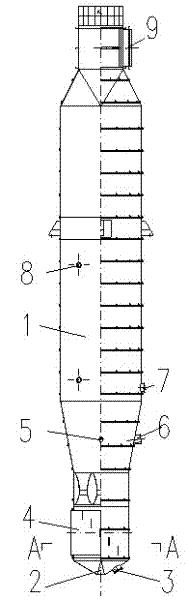
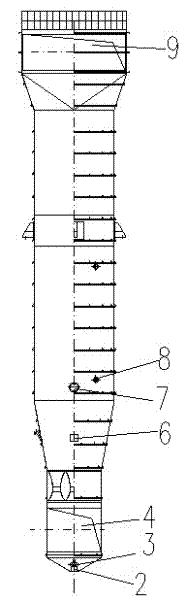
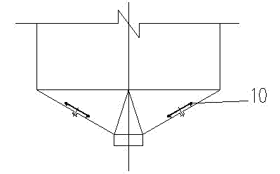
[0024] Below in conjunction with accompanying drawing, the present invention is described in detail, as figure 1 as shown, figure 2 As shown, a flue gas desulfurization tower of the present invention includes a tower body 1 composed of a flue chamber, a spray chamber and a desulfurization chamber, and a desulfurization slag outlet 2, an ash opening 3 and a flue gas outlet are arranged at the lower part of the tower body 1. Inlet 4, return ash inlet 6, desulfurizer inlet 5 and nozzle interface 8 are arranged in the middle of tower body 1, flue gas outlet 9 is arranged at the upper end of tower body 1, between desulfurization slag outlet 2 and flue gas inlet 4 The gap is the desulfurization tower outlet necking section, the necking section is in the shape of a sky circle, and an annular air distribution device 10 is arranged on the inner circular cone slope of the necking section, see image 3 and Figure 4 , the air distribution device 10 has an air outlet with the wind dire...


PUM


Abstract

The invention discloses a flue gas desulfurizing tower, which comprises a tower body. A desulfurized slag outlet, a poking opening and a flue gas inlet are arranged on the lower part of the tower body; a returning ash inlet, a desulfurizer inlet and a nozzle port are arranged in the middle of the tower body; a flue gas outlet is arranged on the upper end of the tower body; and a desulfurizing tower outlet necking section is arranged between the desulfurized slag outlet and the flue gas inlet. The flue gas desulfurizing tower is characterized in that: an annular air distributing device is arranged on an internal sloping face of the necking section and is provided with an air outlet with the wind direction sloped upwards. According to the flue gas desulfurizing tower, the air distributing device is arranged on the necking section, so that fly ash falling from the tower is blown to be remixed with the flue gas, not only can the fly ash be blown, but also the fluency of distribution in the tower can be improved through the action of airflow, and the desulfuration efficiency is improved.

Description

technical field [0001] The invention belongs to the technical field of chemical equipment, in particular to a desulfurization tower for flue gas treatment. Background technique [0002] Harmful gases such as sulfur dioxide and nitrogen oxides in the flue gas produced when coal, oil, and gas are burned are discharged into the atmosphere, causing acid rain, destroying the ecological environment, and affecting human health. In response to the more stringent control standards proposed by my country's relevant environmental protection regulations on the allowable emission concentrations of sulfur dioxide and nitrogen oxides in flue gas, various flue gas desulfurization technologies, methods and devices have emerged as the times require. [0003] Coal-fired SO2 control methods can be divided into three categories: desulfurization before combustion, desulfurization during combustion, and desulfurization after combustion (flue gas desulfurization), among which flue gas desulfurizati...

Claims


Application Information

Patent Timeline
Patent Type & Authority Applications(China)
IPC IPC(8): B01D53/83B01D53/50
Inventor 黄震邵亚锋缪缓钰
Owner 江苏佳鑫环保工程有限公司
Why Eureka
Try Eureka