Reinforcement cage cement plaster pile casing for sea reclamation fill geological basement and construction process thereof

A steel skeleton and cement mortar technology, which is applied in the direction of basic structure engineering, construction, sheet pile walls, etc., can solve the problems that affect the construction period, easily cause collapse, and the foundation of the foundation pit is not stable enough, so as to prevent the outflow of mud, control overfilling, The effect of preventing collapse

Active Publication Date: 2012-06-27
HUAHAI ENG CO LTD OF CREC SHANGHAI
6 Cites 4 Cited by

AI-Extracted Technical Summary

Problems solved by technology

However, this method is easily affected by environmental conditions such as tides and affects the cons...

Method used

1, utilize the comprehensive principle of mortar pressure resistance, waterproof, barbed wire sheet consolidated mortar, reinforced skeleton overall stress, make and apply reinforced reinforced cement mortar casing, undertake the evenly distributed circumferential lateral pressure that water and soil produce, with To ensure the balance of the geological structure.
5, the suspension ring of reinforced skeleton cement mortar casing adopts Q235 round steel, and ...

Abstract

The invention relates to the technical field of civil engineering and construction, in particular to a reinforcement cage cement plaster pile casing and a construction process thereof. The reinforcement cage cement plaster pile casing comprises twisted steel, iron wire meshes and cement plaster, and is characterized in that the reinforcement cage cement plaster pile casing is a cylinder in shape; the cylinder is provided with a plurality of longitudinal cage ribs arranged at equal distance; the longitudinal cage ribs arranged at equal distance are provided with a plurality of toroidal cage ribs arranged at equal distance; the longitudinal cage ribs arranged at equal distance and the toroidal cage ribs arranged at equal distance are respectively provided with inner layer iron wire meshes and outer layer iron wire meshes; and the iron wire meshes are provided with the cement plaster. The reinforcement cage cement plaster pile casing has the advantages that equipment for driving and extracting a steel pile casing or reinforcement treatment is not needed, thereby, the process is simple, and the working hour is saved; a top soft soil layer can be effectively prevented from collapsing; concrete overfilling is controlled, thereby, resources are saved; a basement is stable, environmentally friendly and is safe and reliable; and the project process is ensured.

Application Domain

Technology Topic

Image

  • Reinforcement cage cement plaster pile casing for sea reclamation fill geological basement and construction process thereof
  • Reinforcement cage cement plaster pile casing for sea reclamation fill geological basement and construction process thereof
  • Reinforcement cage cement plaster pile casing for sea reclamation fill geological basement and construction process thereof

Examples

  • Experimental program(1)

Example Embodiment

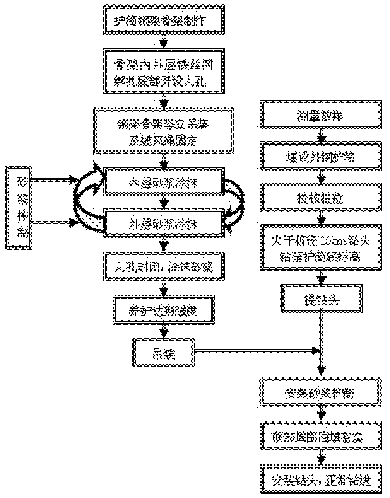
[0022] The present invention will be further explained in conjunction with the accompanying drawings. The manufacturing technology and process flow of this device are very clear to those in the field.
[0023] 1. Production of reinforced cement mortar protection tube
[0024] 1) Construction and production of steel skeleton
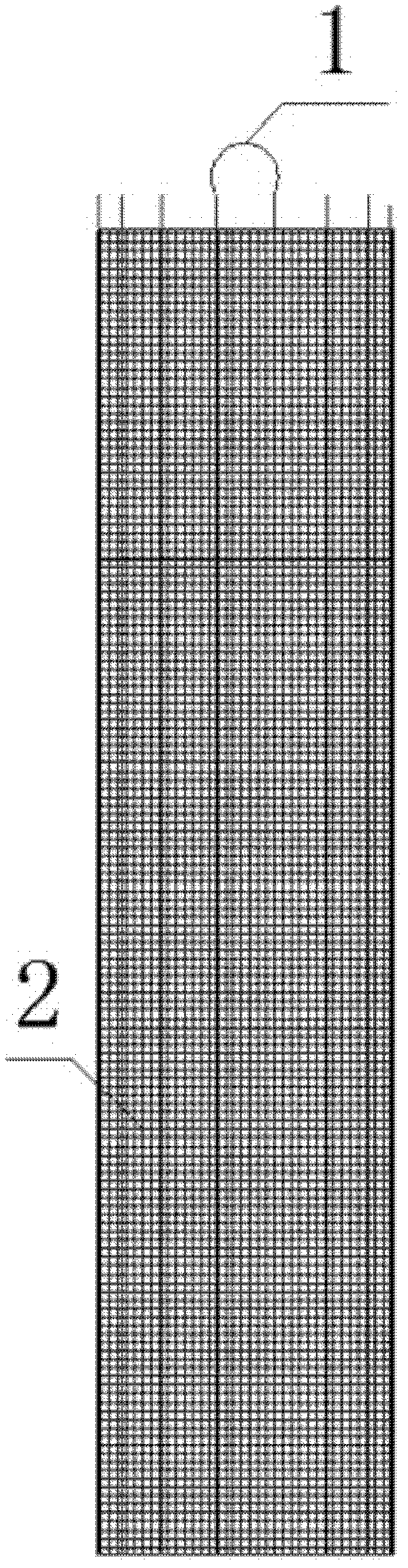
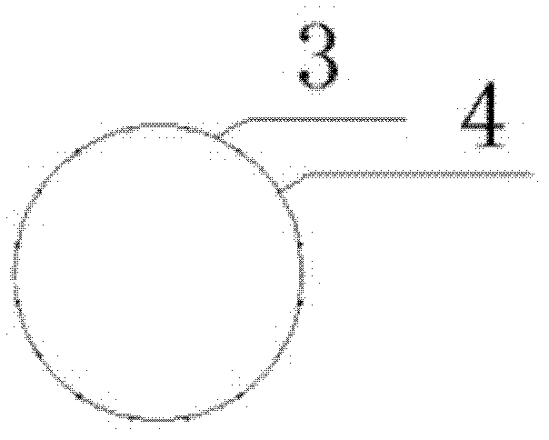
[0025] Generally designed for bored piles with a diameter of 1.5m, the steel-reinforced cement mortar protective cylinder adopts Φ25 threaded steel bar in the circumferential direction, and is arranged along the length of the protective cylinder from 1.7m to 2m. Double-sided lap welding is adopted; 16 longitudinal framework bars are used. Φ16 threaded steel bars are uniformly distributed and welded on the outside of the circumferential skeleton steel bars; the tops of two longitudinal steel bars in any diameter direction are welded with lifting rings. The length of the steel frame is considered based on the ground elevation of the drilling platform minus the elevation of the bottom of the soft soil layer plus 30cm embedded in the hard soil layer. In this design, the ground elevation is 1.5m, the top elevation of the hard soil layer is -3.2m, and the length of the steel frame is 1.5-(-3.2)+0.3=5m. The diameter of the steel frame is 22cm larger than the design aperture. The steel frame is made at the processing site of the bored pile steel cage.
[0026] 2) Barbed wire banding
[0027] The barbed wire mesh is 5mm×5mm, and the barbed wire mesh is two layers, which are distributed inside and outside the framework. After the steel frame is made, the barbed wire mesh is bound at the processing site. Use commonly used tie wires to pass through the grid and tie them to the longitudinal and circumferential skeleton ribs. The tie spacing is between 10 cm and 15 cm. The tie wire joints are bent to the inside. The upper and lower overlap and closed overlap should be greater than 5 cm. The framework can be tied in the horizontal state of the processing site, or the framework can be transported to the vicinity of the pile hole and erected and fixed with a cable wind rope tie before binding. In order to facilitate the application of mortar on the inner side after erection, manholes should be opened at the bottom for workers and mortar to enter and exit.
[0028] 3) Transportation and erection of steel frame
[0029] Use the steel cage transport tool to transport the steel frame to the vicinity of the hole, use a truck crane to hang it on the flat and compacted ground, and use the iron wire as a cable wind rope to tie the four corners of the frame to prevent the mortar from overturning during the operation.
[0030] 4) Mortar mixing and application
[0031] The mortar ratio is sand: cement=3:1, using P.O32.5 composite Portland cement, mixed on-site manually, and the final strength is required to reach M7.5. After the internal and external mortar is applied, the thickness is greater than 40mm. The mortar application is carried out from bottom to top, first from inside to outside, within one half of the range between every two ring frame ribs as a closed area. When applying, the next batch of shovel follows the previous batch of shovel from bottom to top, first light and then heavy, lift up, and repeat more than 2cm, so that the inner mortar forms a ring-shaped whole, so that there are no pinholes and no broken joints at the joints. If the mortar on the inner side has initially set, the outer side can be applied. To smear to a certain height, the work ladder frame needs to be hoisted into the frame, and a ladder frame is set outside, and two workers can complete the smearing operation simultaneously or by one person. After painting the inside, close the manhole, paint the inside of the manhole, lift the ladder frame, and paint the outside of the manhole.
[0032] 5) Maintenance
[0033] The reinforced cement mortar protective cylinder can be hoisted after it reaches 70% of its design strength after being cured by spraying water.
[0034] 2. Embedding of jacket steel tube
[0035] When burying the outer steel protective tube, measure and loft the pile position first, and then manually excavate and bury the outer steel protective tube. The height of the steel casing is only 2m, and the hole surrounding the hole should be densely packed with cohesive soil after burying. The inner diameter of the steel protective cylinder is more than 40cm larger than the design aperture. The role of the steel protective tube is to prevent the hole from collapsing during the drilling of the large bit and to ensure the accurate positioning of the mortar protective tube.
[0036] 3. Hoisting of reinforced cement mortar protection tube
[0037] Use a positive circulation drill with a tiltable bracket to drill the hole. The diameter of the drill bit is 20cm larger than the designed hole diameter. When drilling through the easily collapsed soil layer and entering the lower silt layer 10-15cm, you can stop drilling, lift the drill bit, dump the frame, and use a truck crane. Hoist the reinforced-frame cement mortar protection cylinder into the hole, and fill the outer void of the cylinder with cohesive soil within about 1m from the top. Key points: The pile frame must be able to be dumped. If other drilling rigs are used, the drilling rig needs to be moved; the reinforced concrete mortar protection tube can be lifted only after it reaches the strength. To avoid long-distance transportation, it is advisable to apply mortar and maintain near the pile position; During the resetting process, the drill must be fixed, and the pile position must be corrected after the drill bit is replaced; the buried depth of the reinforced frame cement mortar protection tube must enter the hard soil layer. It is appropriate that the top is slightly lower than the outer protective tube 20cm.
[0038] 4. Install the drill bit and drill normally
[0039] After the reinforced frame cement mortar protection tube is buried, the pile frame can be restored and the normal drill bit can be used to drill.
[0040] Process principle
[0041] 1. Using the comprehensive principle of pressure resistance and waterproofing of mortar, barbed wire consolidation mortar, and the overall force of the steel frame, the steel frame cement mortar shell is made to bear the uniform circumferential lateral pressure generated by the water and soil to ensure the geological structure Balance.
[0042] 2. Using the principle that the drill can replace the drill bit, first use a large-diameter drill bit to drill to the depth of the buried hole of the protective tube, then hoist the reinforced skeleton cement mortar protective tube into place, then replace the normal drill bit for drilling.
[0043] This construction method is applicable to:
[0044] 1. The construction of bored piles in the newly formed land area near the sea, the surface layer is easily collapsed, and the ditch, pond and river course.
[0045] 2. This construction method needs to replace the drill bit and install the reinforced cement mortar protective cylinder, which is suitable for the positive circulation drill with the pile frame to be dumped. Other drilling rigs need to be moved and repositioned after installing the protective tube.
[0046] 3. The reinforced-frame cement mortar protection tube reduces the frictional resistance of the pile top, and is suitable for the construction of friction piles and end-bearing piles where the design of the top frictional resistance is not considered.
[0047] Key points:
[0048] The pile frame must be able to dump. If other drilling rigs are used, the rigs need to be moved. During the dumping and resetting of the pile frame, the drill must be fixed, and the pile position must be corrected after the drill bit is replaced. In order to avoid long-distance transportation, it is advisable to apply mortar near the pile site and maintain it. The reinforced-frame cement mortar protection tube can only be lifted until its strength is reached. It is advisable to bury the reinforced-frame cement mortar protective cylinder at the top slightly below the outer steel protective cylinder by 20cm, and the bottom should enter the hard soil layer by 15m-20m.
[0049] The key points of quality control of this construction method are:
[0050] 1. The wire mesh inside and outside needs to be bound and bound firmly with the frame;
[0051] 2. The reinforced-frame cement mortar protective tube needs to be made in advance, and the strength must be reached before hoisting;
[0052] 3. The drill bit used for embedding the steel protective tube needs to be larger than the design hole diameter of 40cm, and the drill depth enters the hard soil layer. If the top part collapses during the construction process, it can not be treated. A large number of collapses can be backfilled and then opened. The mortar protection tube needs to be buried deep, and the external voids of the protection tube need to be densely packed with clay. The top of the reinforced cement mortar protective tube is lower than the outer steel protective tube to ensure that the mud does not flow turbulently when the concrete is poured.
[0053] 4. The main function of the outer steel protective tube is positioning. Its outer diameter is greater than the pile diameter by 40cm, and the plane position should be accurate.
[0054] Safety and environmental protection measures:
[0055] 1. After the steel-reinforced cement mortar protection tube is finished, the strength must be reached before it can be hoisted to prevent damage.
[0056] 2. After the frame is erected, cable wind ropes in four directions must be installed to prevent the frame from falling.
[0057] 3. It is advisable to use the fork-split ladder frame for mortar smearing operations, and the bottom is tied to prevent personnel from falling due to opening.
[0058] 4. Confirm that the buried deep hole of the reinforced cement mortar protective tube reaches the hard soil layer to prevent the reinforced cement mortar protective tube from sinking.
[0059] 5. The lifting ring of the reinforced cement mortar protection cylinder adopts Q235 round steel. The lifting point needs to be designed and welded. The lifting capacity of the lifting equipment, the angle of the boom, and the equipment station are subject to safety inspection and confirmation. The lifting process is directed by the cable workers. Ensure safety.
[0060] 6. Workers' self-protection awareness should be strengthened. After the manhole is closed, the reinforced-frame cement mortar-protected cylinder escalator, and personnel need to be equipped with safety protection appliances when going out.

PUM

PropertyMeasurementUnit
Length<= 9.0m
Aperture22.0cm
tensileMPa
Particle sizePa
strength10

Description & Claims & Application Information

We can also present the details of the Description, Claims and Application information to help users get a comprehensive understanding of the technical details of the patent, such as background art, summary of invention, brief description of drawings, description of embodiments, and other original content. On the other hand, users can also determine the specific scope of protection of the technology through the list of claims; as well as understand the changes in the life cycle of the technology with the presentation of the patent timeline. Login to view more.

Similar technology patents

Classification and recommendation of technical efficacy words

  • Simple process
  • Prevent collapse

Stent delivery system and method of use

ActiveUS20060184224A1Prevent collapseBronchoscopesStentsVisual observationEndoscope
Owner:BOARD OF RGT THE UNIV OF TEXAS SYST

Seismic isolation apparatus

InactiveUS20060137264A1Prevent collapseStable damping capabilityStands/trestlesKitchen equipmentRubber ringEngineering
Owner:BRIDGESTONE CORP

Method and apparatus for treating sleep apnea

ActiveUS20150190630A1Reduces occurrence and/or severityPrevent collapseHead electrodesSnoring preventionPalatoglossus muscleTreatment sleep
Owner:INVICTA MEDICAL
Why Eureka
Try Eureka