Electromagnetic valve and electromagnetic valve system

A solenoid valve and valve cavity technology, applied in the direction of lift valve, valve detail, multi-way valve, etc., can solve the problem of low operating frequency of the electromagnetic valve, achieve the effect of reducing the travel distance, increasing the operating frequency, and shortening the closing time

Active Publication Date: 2012-06-27
HEFEI MEIYA OPTOELECTRONICS TECH
View PDF7 Cites 9 Cited by
  • Summary
  • Abstract
  • Description
  • Claims
  • Application Information

AI Technical Summary

Problems solved by technology

[0005] In view of this, the present invention provides a solenoid valve and a solenoid valve

Method used


Image

  • Electromagnetic valve and electromagnetic valve system
  • Electromagnetic valve and electromagnetic valve system
  • Electromagnetic valve and electromagnetic valve system

Examples


Example Embodiment

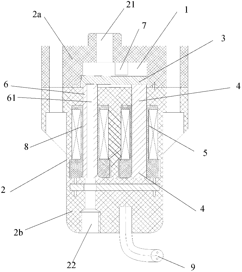
[0086] Among them, the present invention also provides a solenoid valve embodiment 3. In this embodiment, the first pillar of the solenoid valve is also an iron core wound with a second coil. This embodiment is different from the solenoid valve embodiment 2. The point is that the circuit connection structure of the first coil and the second coil are different.

[0087] See Figure 5 , Shows a schematic diagram of the circuit connection inside the solenoid valve in the third embodiment.

[0088] The second coil 8 is connected in series with a diode 82 that blocks forward current, and then connected in parallel to both ends of the first coil 5.

[0089] After the first coil 5 and the second coil 8 are connected in parallel, they can be directly connected to an external power source. Preferably, the switch pulse control circuit 200 can also be connected through the built-in switch 300, and the external power source is connected through the switch pulse control circuit 200. When the sol...


PUM


Abstract

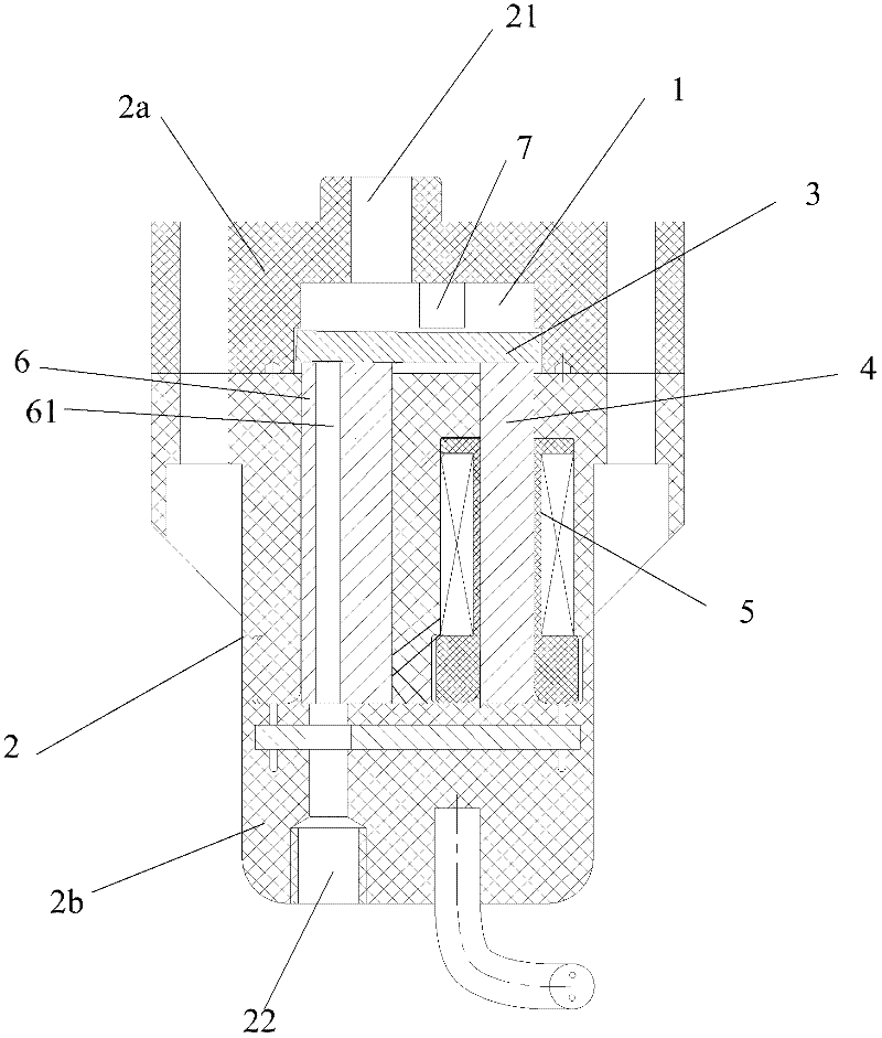
The invention provides an electromagnetic valve and an electromagnetic valve system. The electromagnetic valve comprises a valve body provided with a valve chamber. A medium inlet communicated with the valve chamber is arranged at one end of the valve body and a medium outlet communicated with the valve chamber is arranged at the other end of the valve body. The electromagnetic valve further comprises a movable piece of the valve and a first iron core fixed at one end of the medium outlet of the valve body and wound with a first coil. A first pillar extending to the valve chamber is arranged at one end of the medium outlet of the valve body. The first pillar is provided with a through hole communicated respectively with the medium outlet and the valve chamber. The movable piece of the valve is located in the valve chamber and presses the first pillar under the effect of medium pressure difference between inside and outside of the valve chamber, forms a seal pair with the first pillar and a gap is formed between the movable piece and the first iron core. The first coil under electrified state generates an electromagnetic force that makes the movable piece of the valve rotate along a pivot so that one end of the movable piece of the valve is attracted away from the first pillar and the other end is adsorbed on the first iron core. The electromagnetic valve and the electromagnetic valve system provided by the invention improve the working frequency and the service life of the electromagnetic valve.

Description

technical field [0001] The invention relates to the technical field of electromagnetic equipment, and more specifically relates to an electromagnetic valve and an electromagnetic valve system. Background technique [0002] Solenoid valve is an industrial equipment that uses electromagnetic effect to realize control function. [0003] Existing solenoid valves generally include a valve body provided with a valve cavity, a valve seat, a valve moving plate, and an electromagnet formed by a coil and an iron core, wherein the valve body is provided with a medium inlet and a medium outlet communicated with the valve cavity; The iron is fixed on the side where the valve body is provided with the medium inlet; the valve seat is fixed on the side where the valve body is provided with the medium outlet, and the valve seat is provided with a through hole, which communicates with the valve cavity and the medium outlet of the valve body respectively; The sheet and the valve seat form a s...

Claims


Application Information

Patent Timeline
IPC IPC(8): F16K31/06F16K1/36F16K11/22
Inventor 张珀田明林茂先
Owner HEFEI MEIYA OPTOELECTRONICS TECH
Why Eureka
Try Eureka