Supercooling plate heat exchanger

A plate heat exchanger and subcooling technology, applied in the direction of heat exchanger type, indirect heat exchanger, fixed plate conduit assembly, etc., can solve the problems of insufficient heat exchange and low degree of fluid turbulence, and improve heat exchange. Efficiency, increasing turbulence, increasing subcooling effect

Inactive Publication Date: 2012-06-27
GUANGZHOU INST OF ENERGY CONVERSION - CHINESE ACAD OF SCI
View PDF6 Cites 1 Cited by
  • Summary
  • Abstract
  • Description
  • Claims
  • Application Information

AI Technical Summary

Problems solved by technology

However, the arrangement of ribs on the plates of traditional plate heat exchangers is that the angle between the ribs and ribs of the general plates and the macroscopic flow direction is fixed, which is a value between 0 and 90 degrees, so that the fluid on the plates The degree of turbulence is low and the heat transfer is not sufficient

Method used


Image

  • Supercooling plate heat exchanger
  • Supercooling plate heat exchanger
  • Supercooling plate heat exchanger

Examples


Embodiment 1

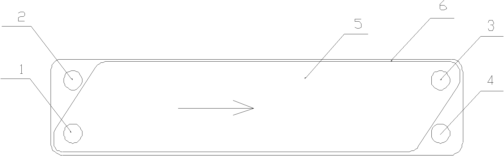
[0019] Such as figure 1 As shown, the direction of the arrow is the macroscopic flow direction of the fluid, the shown dotted line is the concave rib 11, and the shown solid line is the protruding rib 10, as figure 1 As shown, in the supercooled plate heat exchanger of the present invention, the two ends of the main body of the heat exchanger are provided with the cold flow side outlet 2 and the cold flow side inlet 4, and also include heat exchange with the hot flow side outlet 3 and the hot flow side inlet 1 respectively arranged at both ends. Area 5, a sealing member 6 is provided on the side of the heat exchange area 5. Therefore, the sealing member 6 allows the hot fluid to enter from the hot flow side inlet 1, pass through the heat exchange area 5, and flow out from the hot flow side outlet 3. The sealing member 6 prevents the hot fluid from flowing to the cold side. Flow side outlet 2 or cold flow side inlet 4;

[0020] Such as figure 2 As shown, the figure is a trad...

Embodiment 2

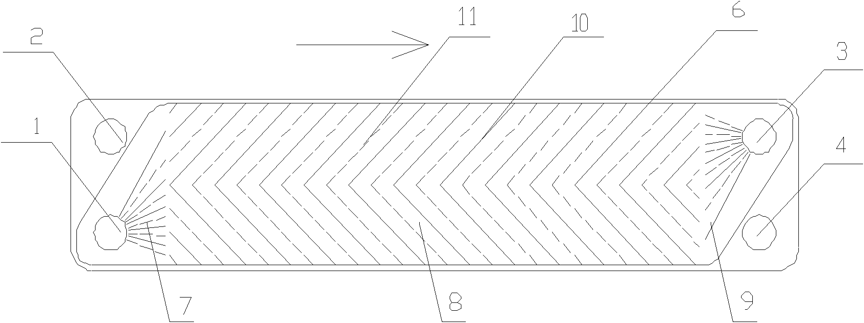
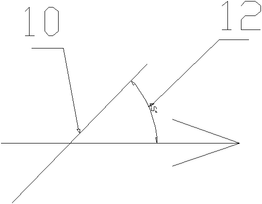
[0027] Such as Figure 5 As shown, the heat exchange area 5 includes a diffuser area 7, a main heat exchange area 8, and a collection area 9 in sequence between the heat flow side outlet 3 and the heat flow side inlet 1, and the main heat exchange area 8 includes three sections. , the first section 81 is provided with protruding ribs 101 and concave ribs 111 that are symmetrically placed at an angle of 50 degrees to the macroscopic flow direction. The first section 81 is the beginning section of heat exchange. The side inlet 1 flows into the diffuse flow area 7, and begins to cool down in this flow section. The angle between the direction of the rib 101 of the plate and the direction of the macroscopic flow is required to be larger, which is 50 degrees;

[0028] The second section 82 is provided with ribs 2 102 and ribs 2 112 that are placed symmetrically at an angle of 10 degrees to the macroscopic flow direction. The heat exchange fluid (referring to the hot side) in this se...

Embodiment 3

[0032] Such as Figure 6 As shown, the heat exchange area 5 includes a diffuser area 7, a main heat exchange area 8, and a collection area 9 in sequence between the heat flow side outlet 3 and the heat flow side inlet 1, and the main heat exchange area 8 includes three sections. , the first section 81 is equipped with protruding ribs 101 and concave ribs 111 that are symmetrically placed at an angle of 80 degrees to the macroscopic flow direction. The first section 81 is the beginning section of heat exchange. The side inlet 1 flows into the diffuse flow area 7, and starts to cool down in this flow section. The angle between the direction of the rib 101 of the plate and the direction of the macroscopic flow is required to be larger, which is 80 degrees;

[0033] The second section 82 is provided with ribs 2 102 and ribs 2 112 that are placed symmetrically at an angle of 40 degrees to the macroscopic flow direction. The heat exchange fluid (referring to the hot side) in this se...


PUM


Abstract

The invention discloses a supercooling plate heat exchanger, which comprises a heat exchange area with a heat flow side outlet and a heat flow side inlet at two ends respectively. A main heat exchange area is arranged between the heat flow side outlet and the heat flow side inlet of the heat exchange area and comprises at least two sections of areas, convex ribs and concave ribs which are all provided with included angles decreased progressively along the macroscopic flow direction of the fluid on the heat exchange area are arranged in each section of the heat exchange area, and the included angles are acute angles formed between the convex ribs and the macroscopic flow direction. The supercooling plate heat exchanger can improve condensate depression and improve heat exchange efficiency.

Description

Technical field: [0001] The invention relates to the technical field of heat exchange, in particular to a supercooled plate heat exchanger for dynamic ice making. Background technique: [0002] At present, dynamic ice making is that the water at 0°C is subcooled to -2°C in the plate heat exchanger, and then the supercooled water at -2°C leaves the plate heat exchanger and is released from the supercooled state to become an ice-water mixture at 0°C, because the water is in the The surface of the plate heat exchanger does not freeze, and the heat exchange efficiency is very high, so the dynamic ice-making efficiency is better than the static ice-making. [0003] The existing plate heat exchanger can achieve stable water cooling and stability at -2°C. If the water is further overcooled, the state of the supercooled water will be unstable, and the supercooling may be removed in the plate heat exchanger, causing blockage and affecting the continuous flow. ice making. But for dy...

Claims


Application Information

Patent Timeline
Patent Type & Authority Applications(China)
IPC IPC(8): F28D9/02
Inventor 冯自平宋文吉高日新
Owner GUANGZHOU INST OF ENERGY CONVERSION - CHINESE ACAD OF SCI
Why Eureka
Try Eureka