Distributed stress/temperature sensing optical fiber coordinate locating method

A technology of distributed strain and sensing optical fiber, which is applied in the direction of physical/chemical change thermometers, thermometers, and measurement of the change force of optical properties of materials when they are stressed, which can solve the problems of measurement position deviation, elongation, Difficult to deal with and other problems, to achieve the effect of improving accuracy, reducing measurement error, and facilitating processing

Inactive Publication Date: 2012-06-27
CHINA FIRST METALLURGICAL GROUP +1
View PDF4 Cites 8 Cited by
  • Summary
  • Abstract
  • Description
  • Claims
  • Application Information

AI Technical Summary

Problems solved by technology

However, the optical fiber sensing points in one-dimensional coordinates also bring difficulties to the three-dimensional spatial positioning of the measured structure
The data obtained by the distributed sensing optical fiber measurement is meaningful only when it is accurately projected on the measured structure. However, the actual situation is that although most distributed sensing optical fibers are marked with one-dimensional coordinates, the surface has no Label the length coordinates (or the labeling accuracy is more than 1 meter, which cannot meet the requirements for accurate positioning of the coordinates), so it is difficult to correspond to the specific position of the measured structure. Even if there are a small number of centimeter-level length labels for distributed sensing fibers, It will be difficult to meet the measurement accuracy requirements due to the following factors:
[0004] 1. The distributed sensing optical fiber is laid in the structure, usually the surface of the optical fiber will be completely wrapped by glue and other protective materials, so that the coordinate positioning cannot be performed by reading the marked length
[0005] 2. The optical fiber is elongated due to pretension during laying, or the length changes due to other factors, which will cause the difference between the actual length and the marked length, and eventually cause the deviation of the measurement position;
[0006] 3. The difference between the actual length and the marked length of the measuring line composed of distributed sensing optical fibers can no longer be calculated after multiple connections, so it is difficult to carry out precise coordinate positioning in space;
[0007] 4. The positioning error of the signal demodulator will expand as the length of the optical fiber increases, resulting in the inconsistency between the theoretical coordinates of the measurement point and the marked coordinates during long-distance measurement, making the marked coordinates unavailable
[0008] In view of the above reasons, the difficulty of coordinate positioning has reduced the measurement accuracy of distributed sensing optical fiber, so a new technology is urgently needed to accurately determine the coordinates of the optical fiber measurement point corresponding to the specific position of each measured structure

Method used


Image

  • Distributed stress/temperature sensing optical fiber coordinate locating method
  • Distributed stress/temperature sensing optical fiber coordinate locating method
  • Distributed stress/temperature sensing optical fiber coordinate locating method

Examples


Embodiment 1

[0024] Distributed strain / temperature sensing optical fiber coordinate positioning method, it comprises the following steps:

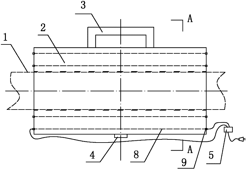
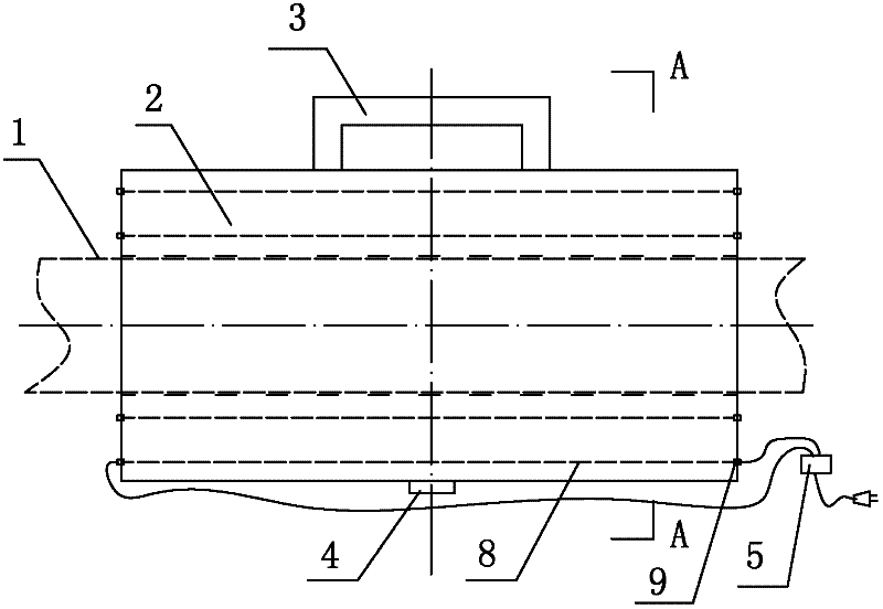
[0025] 1) Arrange distributed strain / temperature sensing optical fiber on the measurement line required by the structure under test (that is, for distributed sensing optical fiber), and set a heating positioning device at the specific position required for measurement of the structure under test, distributed strain / The temperature sensing optical fiber passes through the heating positioning device;

[0026] 2) During measurement, the heating positioning device is energized, and the heating positioning device emits heat to the distributed strain / temperature sensing optical fiber. By changing the ambient temperature of the local optical fiber, the coordinates of the optical fiber measurement point at the specific position required for measurement of the measured structure are obtained. .

[0027] Experiments are carried out according to the above metho...

Embodiment 2

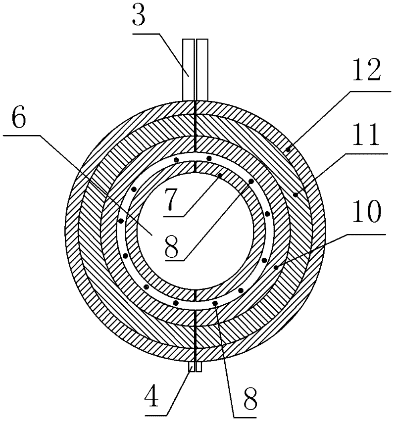
[0035] It is basically the same as Embodiment 1, except that the length of the two semicircular ring members is 5 cm.

[0036] Experiments were carried out according to the method described in Example 1, and the results showed that the accuracy rate reached 100%.

Embodiment 3

[0038] Basically the same as embodiment 1, the difference is: the inner radius of the two semicircular ring members is 0.3cm, the radius of the semicircle ring iron sheet is 1cm, and the outer radius of the two semicircle ring members is 2cm.

[0039] Experiments were carried out according to the method described in Example 1, and the results showed that the accuracy rate reached 100%.


PUM

PropertyMeasurementUnit
diameteraaaaaaaaaa
lengthaaaaaaaaaa
radiusaaaaaaaaaa

Abstract

The invention belongs to the technical field of distributed optical fiber sensing in photoelectric technology and in particularly relates to a locating method capable of measuring corresponding coordinate position of a distributed sensing optical fiber in a measured structure. A distributed stress / temperature sensing optical fiber coordinate locating method is characterized in that the method comprises the following steps: (1) arranging a distributed stress / temperature sensing optical fiber on a to-be-measured circuit of the measured structure, and arranging a heating and locating device at a to-be-measured specific position of the measured structure, and enabling the distributed stress / temperature sensing optical fiber to pass through the heating and locating device; and (2) in a measuring process, electrifying the heating and locating device to emit heat to the distributed stress / temperature sensing optical fiber, and acquiring an optical fiber measuring point coordinate at the to-be-measured specific position of the measured structure. According to the method, the measurement circuit composed of the distributed sensing optical fiber can be subjected to accurate coordinate location, and the optical fiber measurement data can be accurately projected on the specific position of the measured structure, so that the measurement error is reduced.

Description

technical field [0001] The invention belongs to the technical field of distributed optical fiber sensing in photoelectric technology, and specifically relates to a positioning method capable of measuring the corresponding coordinate position of a distributed sensing optical fiber in a measured structure. Background technique [0002] Brillouin Optical Time Domain Analyzer (BOTDA) is a technology that uses the frequency change of light scattered in the optical fiber to measure the change of optical fiber strain (temperature). It can measure temperature and strain simultaneously. Its working principle is: The laser transmitters at both ends of the fiber inject a beam of pulsed light and a beam of continuous light into the fiber respectively. When the frequency difference between the pulsed light and the continuous light is equal to the Brillouin frequency shift of a certain interval in the fiber, the area will be affected. Exciting the Brillouin amplification effect, energy tr...

Claims


Application Information

Patent Timeline
Patent Type & Authority Applications(China)
IPC IPC(8): G01K11/32G01L1/24G01K11/322
Inventor 王平吴梦先丁勇
Owner CHINA FIRST METALLURGICAL GROUP
Why Eureka
Try Eureka