High-precision angle measurement method of automotive anti-collision radar based on interference theory

An anti-collision radar, high-precision technology, applied in the field of radar communication and automotive electronics, can solve problems such as ambiguity in direction angle measurement

Inactive Publication Date: 2012-06-27
BEIJING INSTITUTE OF TECHNOLOGYGY +2
View PDF3 Cites 7 Cited by
  • Summary
  • Abstract
  • Description
  • Claims
  • Application Information

AI Technical Summary

Problems solved by technology

[0003] The purpose of the present invention is to improve the target angle measurement accuracy of the automobile active anti-collision radar, improve the guidance ability of the radar, solve the ambiguity problem of the direction angle measurement, propose a kind of high-precision angle me

Method used


Image

  • High-precision angle measurement method of automotive anti-collision radar based on interference theory
  • High-precision angle measurement method of automotive anti-collision radar based on interference theory
  • High-precision angle measurement method of automotive anti-collision radar based on interference theory

Examples


Embodiment 1

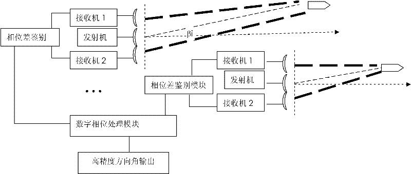
[0044] The working frequency range of the millimeter-wave automotive anti-collision radar in this embodiment is 76GHz-77GHz, and two radar transmitters, two sets of coherent receivers, a phase difference identification module and a corresponding digital phase processor are used.

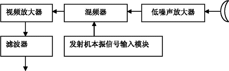
[0045] Each receiver consists of receiving antenna, low noise amplifier, mixer, video amplifier, filter and transmitter local oscillator signal input module, such as figure 2 As shown; the receiving antenna, low noise amplifier, mixer, video amplifier, and filter are connected in sequence, and the output of the local oscillator signal input module of the transmitter is connected to the mixer.

[0046] Wherein, the receiving antenna adopts a standard gain horn antenna, the model is JXTXLB / 12 / 25 / A; the low noise amplifier, the mixer, the local oscillator signal of the transmitter and the radar transmitter module are all integrated in the radio frequency system produced by Infineon Corporation. On the ...

Embodiment 2

[0080] An automobile anti-collision radar system with single transmitter and dual receivers; the working wavelength of the system is 3.9mm, and the distance between the two receiver antennas is 2.8cm. It is obtained that the unambiguous β value is ±4°, which meets the application requirements of the actual vehicle front-sight range for the automotive anti-collision radar system. However, if the distance between the two receiver antennas needs to be increased, resulting in azimuth ambiguity, or serious angular ambiguity when the radar operates at a shorter wavelength.

[0081] If a car collision avoidance radar system with single transmitter and double receiver is used; the working wavelength of the system is 3.9mm, and the distance between the antennas of the two receivers is 8cm. It is obtained that the unambiguous β value is ±2.79°. For this automotive anti-collision radar system, it cannot meet the application requirements of the actual automotive front-sight range, and d...


PUM


Abstract

The invention relates to a high-precision angle measurement method of an automotive anti-collision radar based on an interference theory, belonging to the technical field of radar communication and the automotive electronics. The high-precision angle measurement of the automotive anti-collision radar of the invention is based on the interference theory of long baseline/short wavelength and co-prime wavelength, multiple groups of radar receiving and transmitting devices are used in the method, each group of transmitters provides a common-source, in-phase and uniform-amplitude local oscillator signal for the corresponding receivers thereof, and simultaneously, the group of receivers is composed of approximately same components; corresponding antennae of each group of receivers receive the same echo to form an interference signal, distinguish the generated phase difference and output the processing result to a digital phase processing module; and the processed multiple channel signals are transmitted in a signal transmitting mode that the transmitters transmit the co-prime wavelength/frequency, and direction angle deblurring is realized based on the inference theory, thus, the high-precision direction angle is obtained.

Description

technical field [0001] The invention relates to a high-precision angle measurement method of an automobile anti-collision radar based on the interference principle, and belongs to the technical fields of radar communication and automobile electronics. Background technique [0002] The research on automotive active collision avoidance radar is getting more and more in-depth. At present, the measurement of the direction angle of the target in front of the vehicle relative to the radar is mostly realized by the difference in the amplitude of the multi-channel receiver. It is easy to implement, but the accuracy of angle measurement is low compared to amplitude angle measurement, and because the amplitude of the signal changes greatly during the movement of the target, the stability of angle measurement is not enough, which affects the measurement of the angle of the target in front of the car and the lane where the target is located position determination. The invention applies...

Claims


Application Information

Patent Timeline
IPC IPC(8): G01S13/93G01S13/46
Inventor 卢继华安建平郑晨卜祥元张军田黎育李安培邵立伟
Owner BEIJING INSTITUTE OF TECHNOLOGYGY
Why Eureka
Try Eureka