
Bidirectional direct-current converter with high buck-boost ratio

A technology of bidirectional DC conversion and bidirectional converter, applied in the direction of converting DC power input to DC power output, output power conversion devices, instruments, etc., can solve problems such as high switching frequency, reduce isolation level, and control method is simple and convenient , the effect of reducing electromagnetic interference

Inactive Publication Date: 2012-06-27
NANJING UNIV OF AERONAUTICS & ASTRONAUTICS
View PDF4 Cites 20 Cited by
  • Summary
  • Abstract
  • Description
  • Claims
  • Application Information

AI Technical Summary

Problems solved by technology

[0005] The present invention aims to propose a new bidirectional DC converter topology in which high-voltage terminals are connected in series and low-voltage terminals are connected in parallel on the basis of traditional bidirectional DC converters, in order to solve the problems of high-voltage DC input with high switching frequency, low-voltage and large current. Power conversion problems in output applications

Method used


Image

  • Bidirectional direct-current converter with high buck-boost ratio
  • Bidirectional direct-current converter with high buck-boost ratio
  • Bidirectional direct-current converter with high buck-boost ratio

Examples


Embodiment Construction

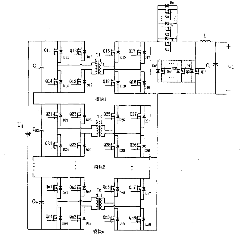
[0015] The main circuit of a bidirectional DC converter with a large buck-boost ratio is as follows: figure 1 As shown in the figure, a combined structure of multiple bidirectional DC transformer modules with high-voltage terminals connected in series and low-voltage terminals connected in parallel, and the primary and secondary side devices of each module and their placement remain symmetrical. After combination, it is cascaded with the subsequent BUCK-BOOST type bidirectional converter. The topology of the bidirectional DC converter with a large buck-boost ratio includes a switch tube, a diode, a power transformer, an output filter inductor, and an output filter capacitor.

[0016] The specific main circuit topology is as figure 1 As shown, it is characterized in that: the front stage of the main circuit is composed of n bidirectional DC transformer modules with the same structure—module No. 1, module No. 2 ... module n, the high-voltage ends of the n modules are connected ...


PUM


Abstract

At present, strong extra-high voltage direct-current electric power transmission grids are built in China. Energy is needed to be stored in a storage battery and then transmitted to the grid or the storage battery is needed to be hung on the direct-current electric power transmission grid because of the randomness of power supply from new energy resources. However, a bidirectional direct-current converter has the characteristic of implementing bidirectional flow of the energy through a set of hardware, so that the bidirectional direct-current converter which is suitable for energy transmission between the high voltage electric power transmission grid and the storage battery becomes a hot topic in the research. The invention provides a bidirectional direct-current converter with high buck-boost ratio, which can be applied to high-voltage and high-power applications. Through the invention, the problem of the flow of the energy among modules after the original bidirectional converter is connected in series or parallel. The circuit of the bidirectional direct-current converter is characterized in that a main circuit is a two-stage bidirectional converter, wherein the front stage is an original-edge inversion auxiliary edge rectification type direct-current converter, and the rear stage is a BUCK-BOOST type bidirectional converter. The control mode is that each module is independently controlled so that staggered-frequency control is realized, electromagnetic interference is reduced and the voltage isolation level of drive signals is effectively lowered.

Description

technical field [0001] The invention relates to a bidirectional direct-current converter with a large step-down ratio, which belongs to medium and high-power direct-current conversion technology in power conversion. Background technique [0002] my country has a vast territory and unbalanced energy distribution and power demand. DC transmission has the advantages of large transmission power and low line loss, and is suitable for long-distance transmission. Therefore, my country needs to establish a strong UHV DC power transmission network. With the depletion of non-renewable energy sources and the intensification of environmental pollution, people have begun to devote themselves to finding and utilizing new and clean renewable energy sources, such as wind energy, solar energy and fuel cells. These new energies must be stored in the battery and then transmitted to the high-voltage DC grid or connected to the DC grid. In order to realize the bidirectional flow of energy betwe...

Claims


Application Information

Patent Timeline
Patent Type & Authority Applications(China)
IPC IPC(8): H02M3/335H02M3/156
Inventor 周峰朱丹陆凯成王慧贞王璐
Owner NANJING UNIV OF AERONAUTICS & ASTRONAUTICS
Learn More