Check patentability & draft patents in minutes with Patsnap Eureka AI!

Photodetector

A photodetector and photoelectric conversion technology, applied in the field of optical communication, can solve the problems of clean signal processing and low signal noise without interference

Inactive Publication Date: 2014-08-20
SHENZHEN GIGALIGHT TECH
View PDF5 Cites 0 Cited by
  • Summary
  • Abstract
  • Description
  • Claims
  • Application Information

AI Technical Summary

Problems solved by technology

However, although this method can reduce the interference signal to a certain extent, it cannot clean the interference signal, and the signal-to-noise ratio of the output signal is low.

Method used


Image

  • Photodetector
  • Photodetector

Examples


Embodiment Construction

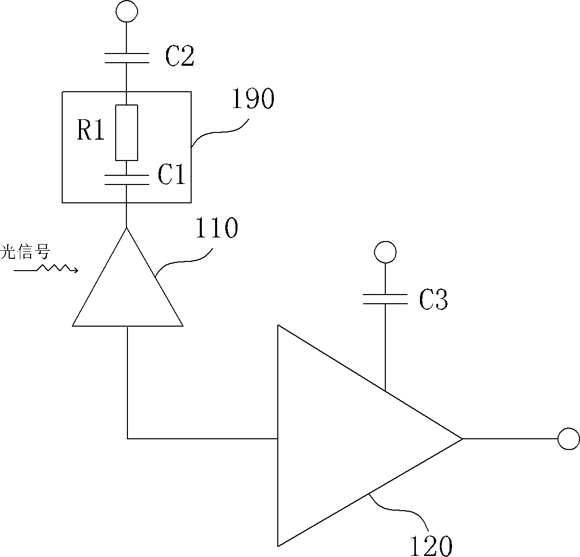
[0018] In order to solve the problem that the power supply of the photoelectric conversion chip has many interference signals, a photodetector capable of eliminating interference is proposed.

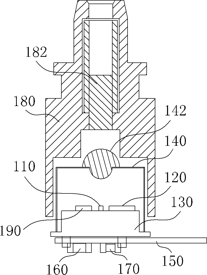
[0019] Such as figure 1 and figure 2 As shown, the photodetector of the preferred embodiment of the present invention includes a mechanical part and a circuit part. The mechanical part includes a platform-shaped tube base 130, a cap-shaped tube cap 140, a flexible plate 150 and an optical fiber coupler 180, and the tube cap The brim of the hat 140 is sheathed on the outer edge of the tube base 130 , and the tube cap 140 is surrounded to form a closed cavity, and a focusing lens 142 is installed at the center of the top of the tube cap 140 . The flexible board 150 is installed on the side of the tube base 130 opposite to the focusing lens 142 . The fiber coupler 180 is arranged on the periphery of the tube cap 140 , and the optical fiber 182 at the center of the fiber coupler 180 is o...


PUM


Abstract

A photodetector comprises a circuit portion. The circuit portion comprises: a filtering chip, a photoelectric conversion chip and a signal preamplifier chip. An output terminal of the filtering chip is connected in series with a power supply input terminal of the photoelectric conversion chip. A signal output terminal of the photoelectric conversion chip is connected with a signal input terminal of the signal preamplifier chip. The filtering chip is integrated by a filtering resistor and a first filtering capacitor which is connected in series with the filtering resistor. By using the photodetector, through the filtering of the filtering chip, interference of an interference signal in a photoelectric conversion chip power supply on the photoelectric conversion chip can be eliminated. A signal to noise ratio of the output signal can be increased.

Description

【Technical field】 [0001] The invention relates to the technical field of optical communication, in particular to an optical detector. 【Background technique】 [0002] In optical communication technology, optical detectors are usually used at the transceiver end of optical fiber transmission to complete the conversion between optical signals and electrical signals. Amplified, and then sent to the signal preamplifier, the integrated amplifier re-amplifies the electrical signal converted and amplified by the photoelectric conversion chip, and then sent to the output of the signal preamplifier for collection. [0003] When the photoelectric conversion chip in the photodetector works, it needs to use the reverse bias voltage as the power supply voltage, and the power supply voltage of the photoelectric conversion chip is generally on the order of tens of volts, and direct power supply will generate more interference signals. To solve the above problems, the traditional method is ...

Claims


Application Information

Patent Timeline
Patent Type & Authority Patents(China)
IPC IPC(8): H04B10/25G01J1/42
Inventor 马强潘儒胜
Owner SHENZHEN GIGALIGHT TECH
Features
  • R&D
  • Intellectual Property
  • Life Sciences
  • Materials
  • Tech Scout
  • Unparalleled Data Quality
  • Higher Quality Content
  • 60% Fewer Hallucinations
Learn More