
Optical module and passive optical network with same

A technology of optical modules and optical network units, which is applied in the field of optical communications, can solve problems such as inability to be widely promoted and applied, increased inventory and management costs, inconvenient installation and maintenance, etc., so as to reduce the complexity of networking and realize wavelength division multiplexing The effect of wavelength division and time division hybrid multiplexing and low cost

Active Publication Date: 2012-06-27
HISENSE BROADBAND MULTIMEDIA TECH
View PDF5 Cites 13 Cited by
  • Summary
  • Abstract
  • Description
  • Claims
  • Application Information

AI Technical Summary

Problems solved by technology

However, because the optical components with wavelength selection function are quite expensive, they are not suitable for use in ONU optical modules at the user end, so they cannot be widely promoted and applied.
Second, to assign a fixed wavelength to each ONU optical module, it is necessary to select an optical module with a specific receiving wavelength for each ONU at the user end. How many ONUs there are, how many optical modules with different structures and functions need to be selected, In addition, each optical module must correspond to the port of the optical multiplexing device during deployment, which leads to not only complex networking, but also inconvenient installation and maintenance, and because the optical modules used are not uniform, resulting in inventory and management costs greatly increase

Method used

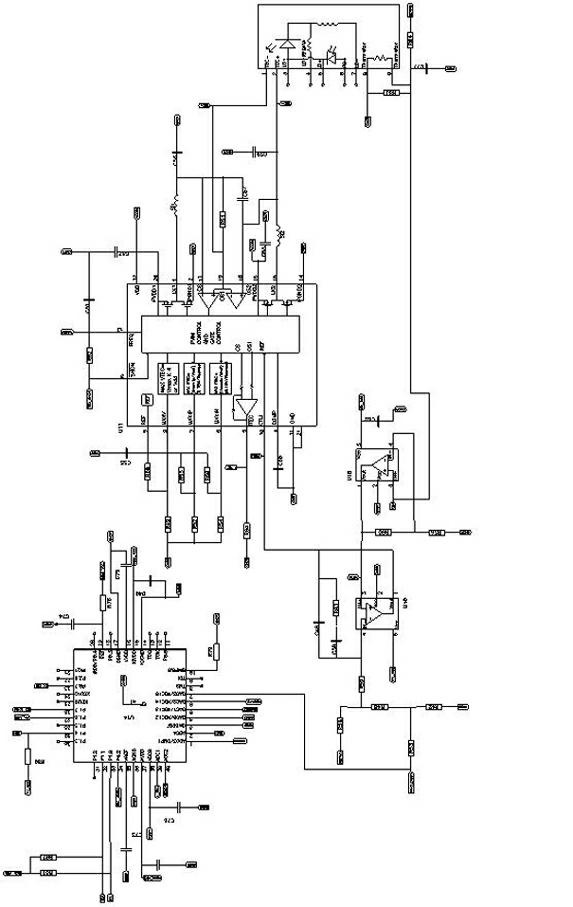
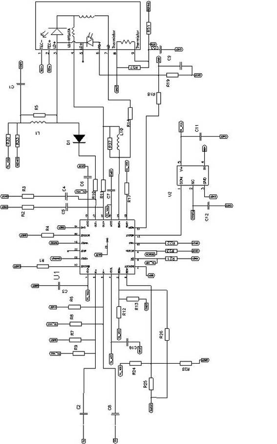

Image

  • Optical module and passive optical network with same
  • Optical module and passive optical network with same
  • Optical module and passive optical network with same

Examples


Embodiment Construction

[0032] The technical solutions of the present invention will be further described in detail below in conjunction with the accompanying drawings and specific embodiments.

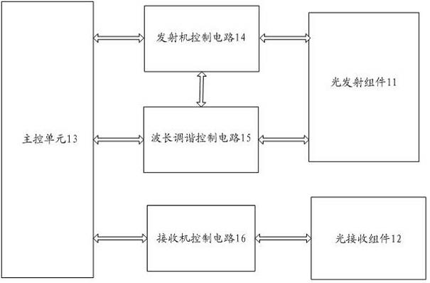
[0033] Please refer to figure 1 , which is a functional block diagram of an embodiment of the optical module of the present invention.

[0034] This embodiment takes the ONU optical module at the optical network unit end as an example, such as figure 1 As shown, the optical module includes a light emitting component 11 and a light receiving component 12 , wherein a temperature controller is integrated in the light emitting component 11 . Wherein, the temperature controller can and is preferably realized by using a semiconductor refrigerator.

[0035] The light emitting component 11 is connected with the transmitter control circuit 14, and the transmitter control circuit 14 provides the driving current and the modulation current of the burst mode for the light emitting component 11, and is controlled by the...


PUM

PropertyMeasurementUnit
Capacitanceaaaaaaaaaa

Abstract

The invention discloses an optical module and a passive optical network with the same. The optical module comprises a master control unit, an optical emitting component integrate with a temperature controller, a temperature controller driving unit and a wavelength tuning unit. By the wavelength tuning unit and the temperature controller driving unit in the optical module, the emitting wavelength of the optical module can be conveniently adjusted by the master control unit of the optical module, wavelength adjustment manner is simple, and difficulty and cost for building the network by optical modules are reduced.

Description

technical field [0001] The invention relates to the technical field of optical communication, in particular to a wavelength tunable optical module and a passive optical network with the optical module. Background technique [0002] Passive Optical Network (PON) is a point-to-multipoint optical fiber transmission and access technology, which originated in the mid-1990s. With the evolution of PON technology, broadband passive optical network (BPON), Ethernet passive Optical Network (EPON) and Gigabit Passive Optical Network (GPON) and other technologies. Passive optical network has developed rapidly because of its broadband, service integration, flexible networking capabilities, and low cost. At present, the commonly used passive optical networks are EPON and GPON. [0003] For EPON and GPON technologies, most of them adopt time-division multiple access (TDM) technology at present, which cannot well meet the rapidly increasing demands of users' bandwidth. Moreover, since the...

Claims


Application Information

Patent Timeline
IPC IPC(8): H04Q11/00H04B10/12H04B10/27
Inventor 赵其圣何鹏杨思更张强薛登山
Owner HISENSE BROADBAND MULTIMEDIA TECH
Learn More