Defogging device for absorption tower

A technology of demisting device and absorption tower, which is applied to the separation of dispersed particles, chemical instruments and methods, separation methods, etc. It can solve the problems of power plant chimney floating, high flue gas flow rate, and blockage of demisters, so as to reduce the phenomenon of carrying , Improve the efficiency of defogging and reduce the effect of gypsum rain

Inactive Publication Date: 2012-07-04
江苏德克环保设备有限公司
View PDF7 Cites 11 Cited by
  • Summary
  • Abstract
  • Description
  • Claims
  • Application Information

AI Technical Summary

Problems solved by technology

[0002] At present, the demisters used in industries such as flue gas desulfurization in China are flat-plate, ridge-type and diamond-shaped demisters. However, due to the complex situation in the actual operation of the site, the phenomenon of floating slurry in the chimney of the power plant often occurs, that is, the so-called gypsum rain
The reasons for the phenomenon of gypsum rain are as follows: First, because the flue gas flow rate processed per unit time exceeds the limit processing capacity that the demister can withstand (that is, the demister can handle the demister without affecting the demisting effect per unit time). The maximum flue gas flow rate to be treated), so that part of the liquid droplets formed on the surface of the demister blades are rolled up and taken away by the flue gas, and then enter the chimney to be discharged into the atmosphere; second, the flue gas flow rate is too high, but the treatment capacity does not exceed In this case, the slurry condensed on the surface of the blade is taken away by the high-velocity flue gas into the chimney and discharged into the atmosphere; third, the demister is blocked, and the slurry is on the demister blade due to poor flushing effect. Scaling causes partial blockage of the mist eliminator, which affects the processing capacity and flue gas flow velocity of the mist eliminator in other through-flow parts, resulting in the occurrence of carryover phenomenon, thus forming gypsum rain

Method used


Image

  • Defogging device for absorption tower
  • Defogging device for absorption tower
  • Defogging device for absorption tower

Examples


Embodiment Construction

[0018] The specific implementation manners of the present invention will be further described in detail below in conjunction with the accompanying drawings.

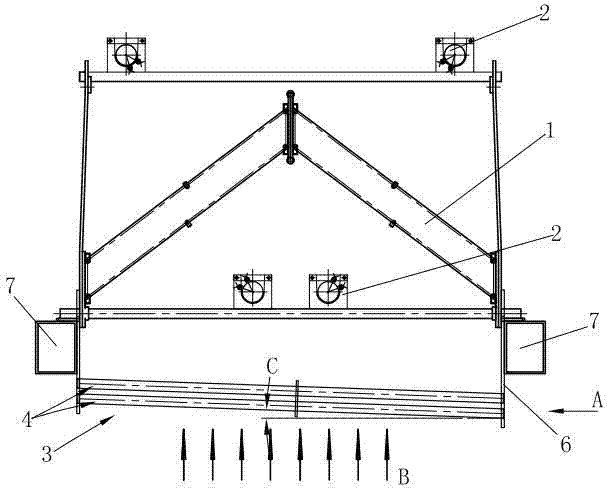
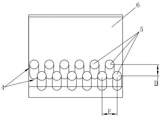
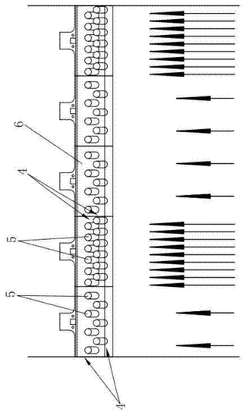
[0019] Such as figure 1 , 2 As shown, the present invention includes at least one of a flat plate demister, a roof demister or a diamond demister installed in a vertically erected absorption tower, figure 1 The middle is the roof type mist eliminator 1, and the cleaning device 2 is arranged on the roof type mist eliminator 1, in the direction of the flue gas flow ( figure 1 Middle arrow B) A pre-mist eliminator 3 is provided upstream of the roof-type demister 1. The pre-mist eliminator 3 includes two layers of pipe rows 4 arranged in parallel, and the pipe row 4 consists of several round pipes 5 arranged in parallel Composition, the round tubes 5 of two adjacent tube rows 4 are arranged in a staggered manner, the round tubes 5 of the pre-mist eliminator tube row are usually PP tubes, and the two ends of the round tubes...


PUM


Abstract

The invention relates to a defogging device for an absorption tower. The defogging device comprises at least one of a flat plate defogger, a ridge defogger or a diamond defogger, and is characterized in that a pre-defogger is arranged at the upstream position relative to the defogger in the flow direction of smoke gas and comprises at least two layers of pipe rows which are arranged in parallel, wherein the pipe rows consists of circular pipes which are arranged in parallel; the circular pipes in the two adjacent layers of pipe rows are arranged in a staggered mode; and the circular pipes in the pipe rows of the pre-defogger are tilted relative to a horizontal plane. According to the defogging device, the pre-defogger is arranged in front of the defogger, part of fog drips in the smoke gas is removed, the treatment capacity of the defogger in the rear is relieved, and smoke gas flow fields in a flue are distributed uniformly by arranging intervals of the pipe rows and intervals of the circular pipes reasonably, so that the defogging efficiency is improved, and the phenomena of carrying and gypsum rain are avoided; and aggregated water drops can be discharged quickly along the circular pipes, so that the water drops which are dripped directly are prevented from being winded up again by the smoke gas or blocking the flowing of the smoke gas.

Description

technical field [0001] The invention relates to a mist removal device, in particular to an absorption tower mist removal device, which is used for the mist removal in the flue gas desulfurization process or other similar processes. Background technique [0002] At present, the demisters used in industries such as flue gas desulfurization in China are flat-plate, ridge-type and diamond-shaped demisters. However, due to the complex situation in the actual operation of the site, the phenomenon of floating slurry in the chimney of the power plant often occurs, that is, the so-called gypsum rain. The reasons for the phenomenon of gypsum rain are as follows: First, because the flue gas flow rate processed per unit time exceeds the limit processing capacity that the demister can withstand (that is, the demister can handle the demister without affecting the demisting effect per unit time). The maximum flue gas flow rate to be treated), so that part of the liquid droplets formed on ...

Claims


Application Information

Patent Timeline
Patent Type & Authority Applications(China)
IPC IPC(8): B01D53/18
Inventor 丁建峰任广超张申新
Owner 江苏德克环保设备有限公司
Why Eureka
Try Eureka