Horizontal combined machine tool with lifting spindle

A technology of combining machine tools and spindles, applied in the field of machinery, can solve problems such as large occupied space and complex machine tool structure, and achieve the effects of large feed force, stable feed and high versatility

Active Publication Date: 2012-07-04
ZHEJIANG XILING
View PDF8 Cites 12 Cited by
  • Summary
  • Abstract
  • Description
  • Claims
  • Application Information

AI Technical Summary

Problems solved by technology

The above-mentioned double-sided horizontal drilling and tapping side plate hole combination machine tool realizes the adjustment of the position of the spindle box through the hydraulic slide table and the column slide table. The problem with this setting is that the structure of the machine tool is complicated and takes up a lot of space.

Method used


Image

  • Horizontal combined machine tool with lifting spindle
  • Horizontal combined machine tool with lifting spindle
  • Horizontal combined machine tool with lifting spindle

Examples


Embodiment 1

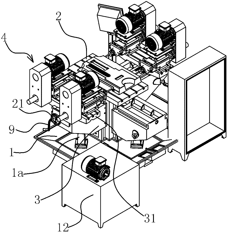
[0032] The vertical and horizontal positions of the spindle box 4 relative to the workpiece can be adjusted according to the processing requirements of the spindle lifting horizontal combined machine tool, and can process the processing requirements of holes in different positions on multiple sides of the workpiece. The spindle lifting horizontal combined machine tool includes a bed 1, a worktable 2, a spindle lifting platform 3, a spindle plate 31, a spindle box 4, a screw 5, a connecting bracket 1a, an adjustment mechanism, a feed mechanism and a drive mechanism.

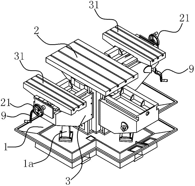
[0033] Specifically, as figure 1 with figure 2 As shown, the workbench 2 is fixedly connected to the bed 1, and the two spindle lifting platforms 3 are respectively located on both sides of the workbench 2, and each workbench 2 is fixedly connected with two spindle boxes 4. Such as image 3 As shown, the bed 1 is fixedly connected with a connecting bracket 1a by bolts, and a threaded hole is processed on the co...

Embodiment 2

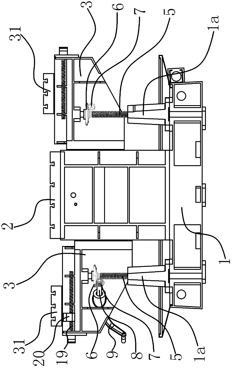
[0040] The technical solution in this embodiment is basically the same as the technical solution in Embodiment 1, the difference is that in this embodiment, the adjustment mechanism includes a bevel gear 6, a bevel gear 2 7 and an adjustment motor, and the bevel gear 1 6 is fixedly connected On the screw 5, the bevel gear 2 7 is meshed with the bevel gear 1 6, the adjusting motor is fixedly connected on the bed 1, the rotating shaft of the adjusting motor is fixedly connected with the bevel gear 2 7, and the bed 1 is also provided with a Motor control buttons. The operator can adjust the height of the main shaft elevating table 3 by pressing the control button, which is convenient to operate.

Embodiment 3

[0042] The technical solution in this embodiment is basically the same as the technical solution in Embodiment 1 or Embodiment 2, the difference is that in this embodiment, the feeding mechanism includes solenoid valve 2, hydraulic station 12 and hydraulic slide table, hydraulic slide The stage is arranged between the spindle box 4 and the spindle plate 31, and the oil inlet and the oil outlet of the hydraulic slide are connected to the hydraulic station 12 through the solenoid valve 2 respectively. The stroke of the hydraulic slide table is longer, and the purchase of the hydraulic slide table is convenient and the cost is relatively low.


PUM


Abstract

The invention provides a horizontal combined machine tool with a lifting spindle, which belongs to the technical field of machinery and solves the problem that a spindle of an existing horizontal drilling and tapping machine tool is incapable of lifting. The horizontal combined machine tool with the lifting spindle comprises a tool body, a working platen and a spindle lifting table, a spindle platen is arranged on the spindle lifting table, a spindle box is arranged on the spindle platen, a connecting support is arranged on the tool body, a screw rod is arranged between the spindle lifting table and the connecting support, one end of the screw rod is fixedly connected with the spindle lifting table, the other end of the screw rod is connected onto the connecting support in a threaded manner, an adjusting mechanism capable of driving the screw rod to rotate is arranged on the spindle lifting table, a feeding mechanism is arranged on the spindle box, and a driving mechanism is arranged between the spindle lifting table and the spindle platen. The vertical distance and the horizontal distance from the spindle platen of the horizontal combined machine tool with the lifting spindle to the working platen can be adjusted, holes aligned to different positions of a plurality of sides of a workpiece can be machined, and the horizontal combined machine tool with the lifting spindle is high in universality.

Description

technical field [0001] The invention belongs to the technical field of machinery, and relates to a combination machine tool, in particular to a main shaft lifting and horizontal combination machine tool. Background technique [0002] Drilling refers to the process of machining a hole on a workpiece with a drill bit. In machining, the hole structure of the workpiece can be processed by a drilling machine tool. According to the processing needs, the processed holes can also be tapped. Usually, drilling and tapping are processed on different machine tools, and when processing holes on different planes on the workpiece, the clamping position of the workpiece needs to be adjusted. Drilling is inconvenient. [0003] In order to solve the above problems, technicians have designed and developed a combined machine tool with multiple spindles. For example, Chinese patent [Patent No. ZL200920042570.1; Authorized Notice No. CN201500882U] discloses a movable template drilling and tappin...

Claims


Application Information

Patent Timeline
Patent Type & Authority Applications(China)
IPC IPC(8): B23P23/02B23B47/26B23B47/22B23Q5/42B23Q5/32
Inventor 周红亮
Owner ZHEJIANG XILING
Why Eureka
Try Eureka