Cooling liquid refluxing system for milling machine
A coolant and milling machine technology, applied in metal processing machinery parts, maintenance and safety accessories, metal processing equipment, etc., can solve the problems of coolant polluting the working environment, affecting the overall appearance of machine tools, secondary pollution of coolant, etc., to improve Reusability, improvement of appearance quality, and effect of reducing leakage
- Summary
- Abstract
- Description
- Claims
- Application Information
AI Technical Summary
Problems solved by technology
Method used
Image

Examples
Embodiment Construction
[0026] The specific implementation of the present invention will be described in further detail below by describing the embodiments with reference to the accompanying drawings, so as to help those skilled in the art have a more complete, accurate and in-depth understanding of the inventive concepts and technical solutions of the present invention.
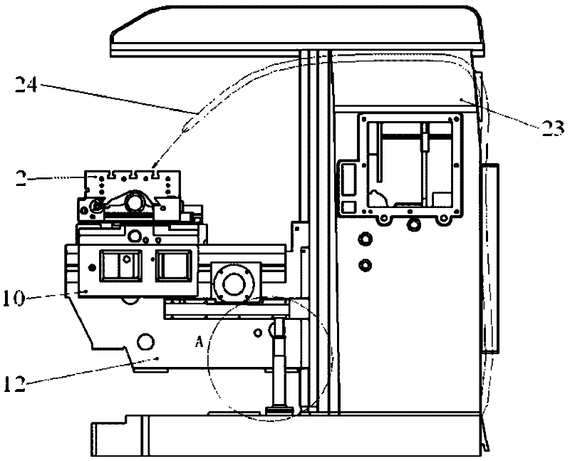
[0027] Such as figure 1 In the milling machine structure expressed, the milling machine includes a bed 23 , a worktable 2 , a rotary table 4 , an elevating table 12 , and an oil outlet pipe 24 . The invention provides a hidden cooling return system for a milling machine.
[0028] In order to solve the problems existing in the current known technology described in the background technology section of this specification and overcome its defects, to achieve the purpose of satisfying the cooling fluid return performance of the machine tool and improving the appearance quality of the machine tool, the technical solution adopted by the p...
PUM
 Abstract
Description
Claims
Application Information
 - Generate Ideas
- Intellectual Property
- Life Sciences
- Materials
- Tech Scout
- Unparalleled Data Quality
- Higher Quality Content
- 60% Fewer Hallucinations
Browse by: Latest US Patents, China's latest patents, Technical Efficacy Thesaurus, Application Domain, Technology Topic, Popular Technical Reports.
© 2025 PatSnap. All rights reserved.Legal|Privacy policy|Modern Slavery Act Transparency Statement|Sitemap|About US| Contact US: help@patsnap.com