Blockage bridging removal machine for ore bin

A technology of mine silo and shed material, applied in the field of blocking shed material clearing machine, can solve the problems of high operating cost, complex structure and high cost, and achieve the effects of strong market competitiveness, simple structure, and convenient processing, installation and use.

Active Publication Date: 2012-07-04
SINOSTEEL MAANSHAN INST OF MINING RES
View PDF6 Cites 5 Cited by
  • Summary
  • Abstract
  • Description
  • Claims
  • Application Information

AI Technical Summary

Problems solved by technology

This patent can solve the problem of blocking the shed material in the mine bin, but t

Method used


Image

  • Blockage bridging removal machine for ore bin
  • Blockage bridging removal machine for ore bin
  • Blockage bridging removal machine for ore bin

Examples


Embodiment Construction

[0020] In order to further describe the present invention, the blockage clearing machine of the present invention will be further described in conjunction with the accompanying drawings and embodiments.

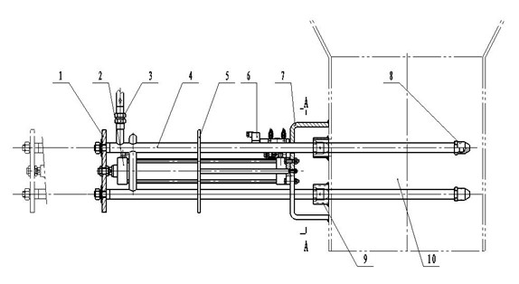
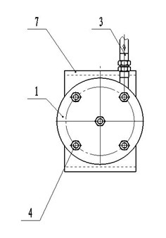
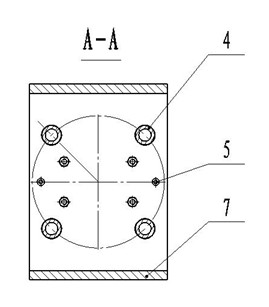
[0021] Depend on figure 1 The main body of the blockage clearing machine of the mine block shed material shown in the present invention is a schematic structural diagram of the top view and combined with figure 2 , image 3 Find out that the present invention is composed of the electromagnetic reversing valve 6 combination of pressurized plate 1, cylinder 2, compressed air inlet pipe 3, smashing device 4, support 7, control cylinder reciprocating. On the piston rod head of the cylinder 2, a circular pressure plate 1 is set, and the pressure plate 1 is fixed to the piston rod head by a large nut. The pressure plate 1 can reciprocate with the piston rod. There are four round holes processed on the pressure plate 1, and the mashing device 4 fixes the mashing device on the pr...


PUM


Abstract

The invention discloses a blockage bridging removal machine for an ore bin, which comprises a pressurization plate (1), a cylinder (2), a compressed air inlet pipe (3), a triturating device (4), a base (7) and an electromagnetic directional valve (6) for controlling reciprocation of the cylinder. A piston rod head of the cylinder (2) is fixedly sleeved on the pressurization plate (1), the triturating device (4) is combined by welding a plurality of mutually parallel triturating rods by an annular round pipe, each triturating rod is a seamless steel pipe, one end of each seamless steel pipe is perpendicularly fixed onto the pressurization plate (1), the other end of each seamless steel pipe is provided with an air nozzle (8) and transversely extends into an ore bin throat section (10) through the base (7), the compressed air inlet pipe (3) is communicated with the seamless steel pipes of the triturating device (4), and the base (7) is fixedly mounted on the side wall of the ore bin throat section (10). Blockage bridging due to sticky rolling balls formed at a bin outlet by sticking excessive thin materials in the ore bin can be thoroughly removed by the blockage bridging removal machine for the ore bin.

Description

technical field [0001] The invention relates to a device for clearing blockages in ore bins, in particular to a blockage clearing machine for reinforced concrete or steel structure ore bins, which can be used for clearing and preventing blockages in ore storage bins in various mine dressing plants. Background technique [0002] At present, the ore dressing plants of various mines are equipped with ore storage bins, which are used to adjust the production process, allocate ore selection paths, adjust the amount of ore input, and balance the ore processing process. [0003] Most of the ore bins adopt reinforced concrete structure or steel structure, and there are rectangular funnel bins or conical funnel bins. When the ore enters the silo, the friction between the ore and the silo wall increases due to different physical factors such as ore moisture content, lumpiness, and surface properties, so the ore cannot slip out of the silo under its own gravity, causing the material to...

Claims


Application Information

Patent Timeline
IPC IPC(8): B65D88/66
Inventor 郝其昌章林吉万健
Owner SINOSTEEL MAANSHAN INST OF MINING RES
Why Eureka
Try Eureka