
Film winding device and method for making optical film employing the same

A manufacturing method and technology of optical film, which are applied in the direction of winding strips, transportation and packaging, thin material processing, etc., can solve the problems of insufficient winding device, increased jitter, and inability to prevent scratches and scratches, and achieve improved performance. The effect of attracting pressure and preventing winding misalignment

Active Publication Date: 2012-07-04
FUJIFILM CORP
View PDF9 Cites 6 Cited by
  • Summary
  • Abstract
  • Description
  • Claims
  • Application Information

AI Technical Summary

Problems solved by technology

[0014] However, conventional film winding devices are not sufficient as winding devices for optical films requiring high planar performance.
[0015] That is, although the winding device of Patent Document 1 is provided with a low-friction resin protruding portion at the tip of the suction nozzle, when the suction pressure of the suction nozzle is increased, the vibration of the film becomes larger, and the occurrence of scratches cannot be prevented.
If the suction pressure is lowered, although the vibration of the film is reduced, the desired winding firmness cannot be obtained
In recent years, as described above, as the width of the optical film increases, the air volume of the associated wind increases, and a suction pressure of 200 Pa or more is required. However, in the winding device of Patent Document 1, when the suction pressure is 200 Pa or more, Increased jitter
[0016] In addition, although the winding device of Patent Document 2 can prevent the vibration of the film, since the pressing roller is in contact with the film surface, it cannot prevent scratches and scratches caused by slipping and the like.
Furthermore, in the case of a wide-width film, it is necessary to form the pressing roll into a crown roll (crown roller), which is prone to wrinkle
[0017] In addition, since the winding device of Patent Document 3 can completely press the winding point in a non-contact manner, it can prevent the occurrence of scratches and scratches as in Patent Documents 1 and 2, but requires high wind pressure, and the cost of blower equipment is very high. high cost
In addition, there are problems such as scattering of surrounding waste materials and generating noise due to wind pressure

Method used


Image

  • Film winding device and method for making optical film employing the same
  • Film winding device and method for making optical film employing the same
  • Film winding device and method for making optical film employing the same

Examples


Embodiment 1

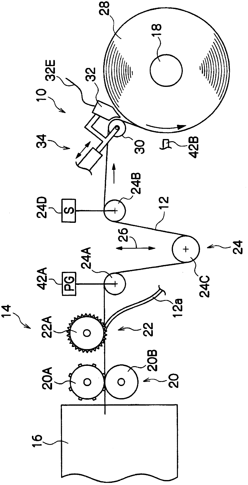
[0133] For the winding device that passed the conditions of the following experiments 1 to 3, the figure 1 A cellulose triacetate film with a width of 2000 mm and a thickness of 80 μm produced in the film production line of the company was wound up.

[0134] (winding condition)

[0135] Experiment 1... is the case of winding without using the backup roll 30 and the suction nozzle 32.

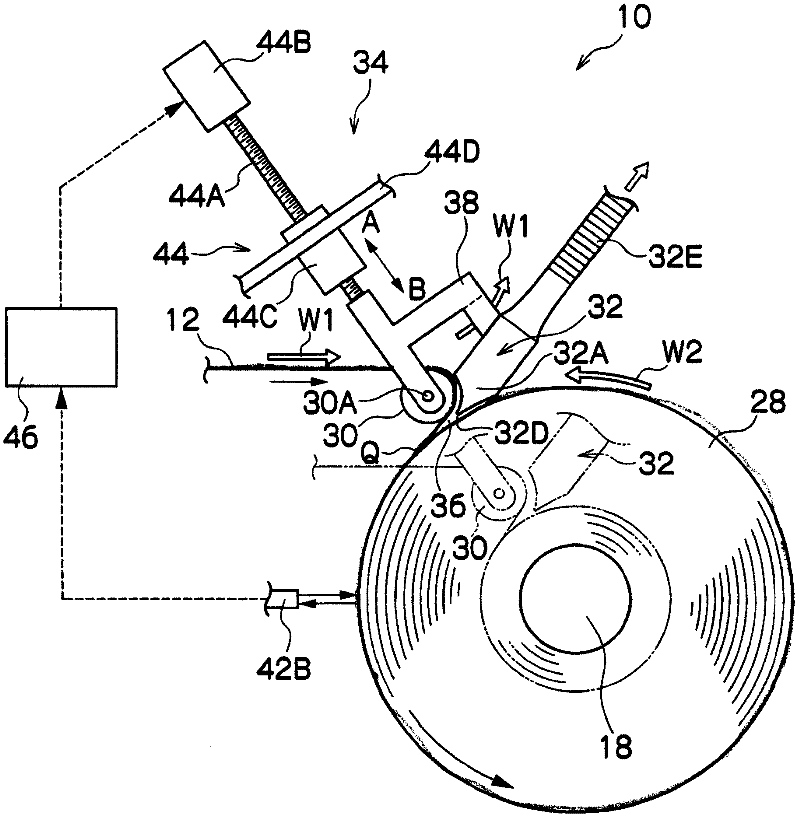
[0136] Experiment 2... is the case where the winding device 10 of this embodiment demonstrated above was used. The gap L1 between the support roll 30 surface and the wrapping roll 28 face is 3 mm, the gap L2 between the support roll 30 face and the side 32B of the support roll side of the suction nozzle 32 is 5 mm, and the side surface of the suction nozzle 32 surrounding the roll roll 28 side The gap L3 between 32C and the surface of the surrounding roll 28 is 5mm. Furthermore, the suction pressure of the suction nozzle 32 was set to 1100 Pa.

[0137] Experiment 3... is the case where the b...


PUM

PropertyMeasurementUnit
Roll diameteraaaaaaaaaa

Abstract

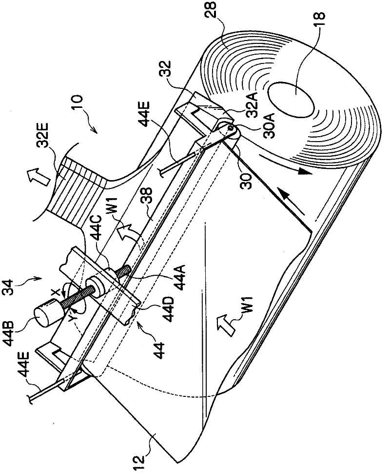
The invention provides a film winding device and a method for making an optical film employing the same. The film winding device (10) winds the movable film (12) upon the winding shaft to form a roller-surrounding object (28), which carries out coiling suspension bearing over the film with the surface pressure above the regulation. Moreover, a triangular-shaped space part (36) is formed by taking the winding starting point as the peak between the coiling suspension bearing film surface and the surface of the roller-surrounding object. The triangular-shaped space part (36) is equipped with an attracting mouth (32) which absorbs the air inside the space part with over-regulated absorbing pressure. Under this condition, the film is wound, suspend, and supported to a support roller (30) in the manner that the surface pressure of the coiling suspension film surface is greater than the absorbing pressure of the absorbing mouth. Moreover, with the changes of the winding diameter of the roller-surrounding object, a moving mechanism is utilized to make the support roller and the absorbing mouth move simultaneously.

Description

technical field [0001] The present invention relates to a film winding device and an optical film manufacturing method using the same, and particularly relates to a winding technique after manufacturing a base film for an optical film. Background technique [0002] For example, optical films such as polarizing plate protective films for liquid crystal display devices, optical compensation films produced through coating and drying of base films, and antireflection films require high planar performance. [0003] A base film such as cellulose triacetate (TAC) is usually formed by a solution film-forming method, and the formed base film is wound by a winding device. Therefore, winding misalignment during winding, winding wrinkles, scratches (including micro-scratches of about 50 μ to 100 μ), deformation of the film end (commonly known as the ear) (knurled portion dented or stretched) ) and other winding failures will become a major problem in quality. [0004] Winding failure ...

Claims


Application Information

Patent Timeline
IPC IPC(8): B65H18/26
Inventor 松村善仁
Owner FUJIFILM CORP
Learn More