Pot-type calcining furnace

A tank-type calciner and calciner technology, which is applied in the field of calciner, can solve the problems of high cost, low heat energy utilization rate, and complex structure, and achieve the effects of high production efficiency, high heat energy utilization rate, and unique structure

Inactive Publication Date: 2012-07-04
许继忠
View PDF7 Cites 5 Cited by
  • Summary
  • Abstract
  • Description
  • Claims
  • Application Information

AI Technical Summary

Problems solved by technology

[0003] The purpose of the present invention is to provide a pot-type calciner to solve the shortcomings of the traditional calciner, such as comp

Method used


Image

  • Pot-type calcining furnace
  • Pot-type calcining furnace
  • Pot-type calcining furnace

Examples


Embodiment Construction

[0018] The present invention will be further described below in conjunction with the accompanying drawings and specific embodiments.

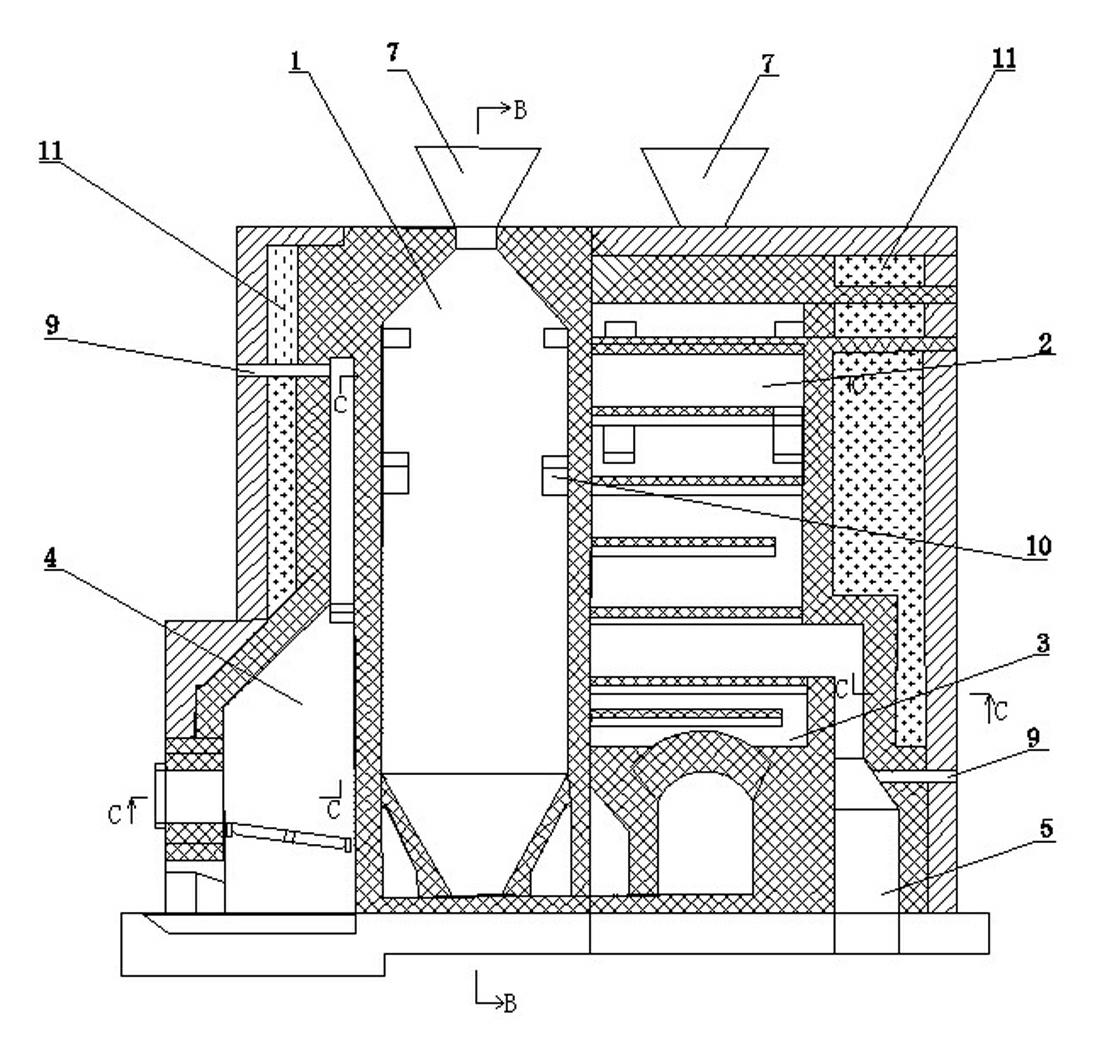
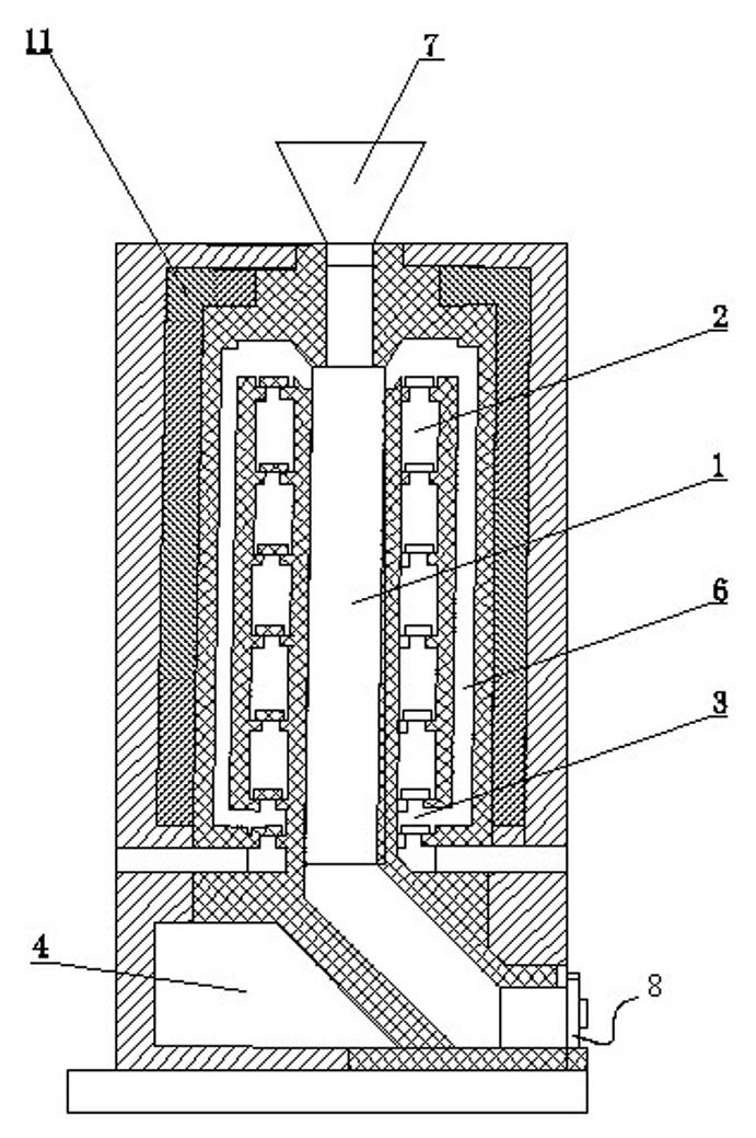
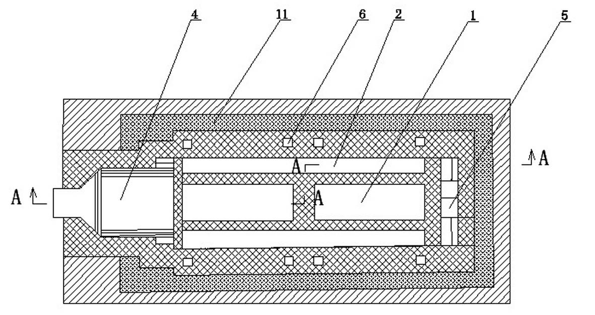
[0019] The structure of the pot calciner is as follows: figure 1 , figure 2 , image 3 shown, of which figure 1 is along image 3 The sectional view of A-A in the middle.

[0020] The pot calciner consists of a calciner 1, a combustion chamber 4, a heating channel 2, an air channel 3, a volatilization channel 6, a flue 5, a feeding system 7 and a discharge system 8. The main structure of the tank type calciner is two vertically arranged calciner tanks 1 arranged left and right, and the specification of each calciner tank is 1520 mm in length x 470 mm in width x 3500 mm in height. There are five layers arranged up and down on the front and rear sides of the calciner 1, and the specifications are 3270 mm long × 240 mm wide × 411 mm high. The heating channel 2 is connected to the combustion chamber 4 at the entrance of the heating channel 2....


PUM


Abstract

The invention discloses a pot-type calcining furnace. The pot-type calcining furnace consists of two calcining pots which are vertically arranged right and left, a combustion chamber, heating fire ways, air ways, volatilizing subways, a flue, feeding systems and discharging systems, wherein the heating fire ways are arranged on the front sides and the back sides of the calcining pots; inlets of the heating fire ways are connected with the combustion chamber, and outlets of the heating fire ways are communicated with the flue; the volatilizing subways are arranged on the peripheries of the heating fire ways; inlets of the volatilizing subways are connected with volatile discharging ports which are formed on the upper parts of the calcining pots, and outlets of the volatilizing subways are communicated with the heating fire ways; and the air ways are arranged below the heating fire ways and are communicated with the volatilizing subways. The pot-type calcining furnace is simple in structure; volatiles decomposed from raw materials are discharged from the discharging ports on the upper parts of the calcining pots, are mixed with air and pre-heated by the heating fire ways, enter the heating fire ways, and are fully combusted and utilized; the heat efficiency of the whole pot-type calcining furnace is high; the production continuity is high; and the production efficiency is high.

Description

technical field [0001] The invention relates to a calcination furnace, in particular to a pot type calcination furnace used for calcination of raw materials in the production of carbon and graphite products. Background technique [0002] In the industrial production of carbon and graphite products, the main equipment used for raw material calcination is the pot calciner. In the prior art, the furnace body of the tank-type calciner is composed of several calciner tanks with the same structure and vertical arrangement made of refractory bricks. Every four calciner tanks form a group, and each calciner mostly consists of three to six groups, that is, twelve to twenty-four calcining pots are included. The main disadvantages of the above-mentioned pot-type calciner are: 1. A large amount of steel is required for infrastructure construction, as well as special-shaped silica bricks and clay refractory bricks with various specifications, and the investment of the pot-type calciner ...

Claims


Application Information

Patent Timeline
IPC IPC(8): F27B14/00F27B14/14F27B14/20F27B14/08F23L15/00
CPCY02E20/34
Inventor 许继忠田雪风
Owner 许继忠
Why Eureka
Try Eureka