
Automatic tester for valve lift and timing phase of engine

An automatic test device and engine valve technology, which is applied in the direction of engine test, measurement device, machine/structural component test, etc., can solve the problem of large volume, inability to measure valve displacement in real time, system volume and configuration difficult to meet the dynamic requirements of the engine, etc. question

Active Publication Date: 2012-07-04
ACADEMY OF ARMORED FORCES ENG PLA
View PDF5 Cites 14 Cited by
  • Summary
  • Abstract
  • Description
  • Claims
  • Application Information

AI Technical Summary

Problems solved by technology

[0004] Although the current electronic control valve device of the engine realizes the control of the valve movement, this control is an open-loop control, which cannot be corrected by measuring the valve displacement in real time. It is the main means of gas volume, and it is also one of the means for the engine to maintain performance indicators in different environments. The adaptive control of valve lift has higher requirements for real-time measurement of valve lift, and automatic testing of valve lift and valve timing is essential.
[0005] Conventional valve lift and valve timing automatic tester is composed of piezoelectric displacement sensor, acquisition card and computer, including valve lift, valve timing data collection and data off-line analysis, this tester has many accessories and is relatively small Large, it is difficult to meet the dynamic requirements of the engine in terms of system volume and configuration

Method used


Image

  • Automatic tester for valve lift and timing phase of engine
  • Automatic tester for valve lift and timing phase of engine
  • Automatic tester for valve lift and timing phase of engine

Examples


Embodiment Construction

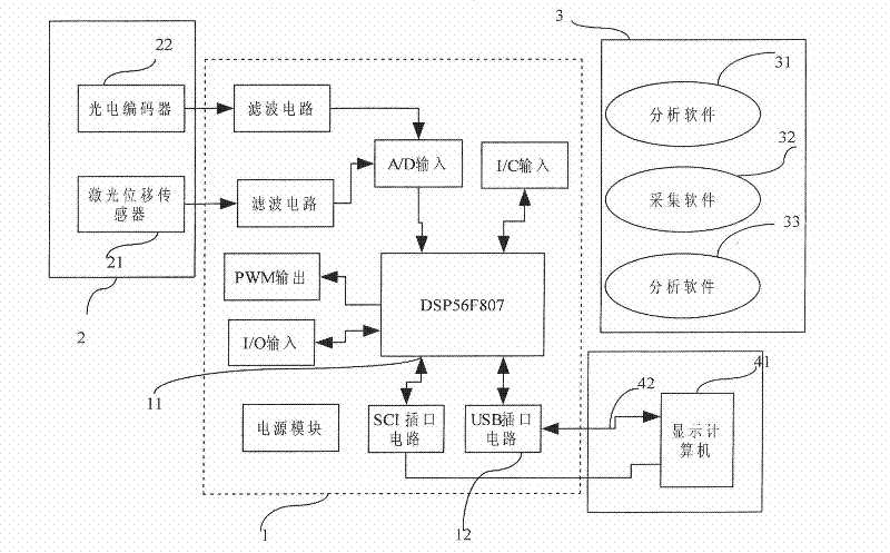
[0027] The engine valve lift and valve timing automatic test device consists of three parts, as attached figure 1 As shown, 1. The hardware of the signal acquisition part is composed of the acquisition unit 1 and the acquisition accessory 2; 2. The system software part 3 is composed of the acquisition software 31, the data analysis software 32, and the data display software 33; 3. The data transmission and display 4 is composed of Data line 41 and display computer 42 form.

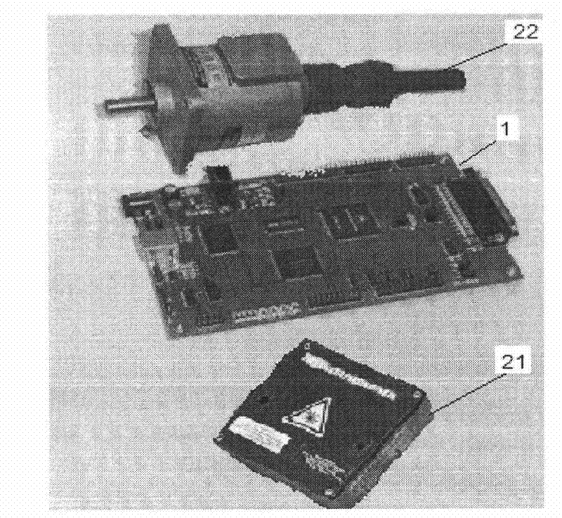
[0028] The acquisition unit 1 is composed of a digital signal processor 11 and a USB plug-in 12, and the acquisition accessory 2 is composed of a laser displacement sensor 21 and a photoelectric encoder 22, as shown in the attached figure 2 shown.

[0029] Digital signal processor 11 selects the digital signal processor DSP56F807 of Freescale Company for use, and it is the special-purpose microprocessor of processing real-time signal, can reach the order execution speed of 40 trillion instructions / S (MI...


PUM


Abstract

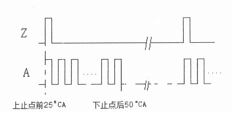
The invention provides an automatic tester for valve lift and timing phase of an engine, consisting of a laser displacement sensor, a photoelectric encoder, a digital signal processor and a display computer, as shown in Figure 1. A newly-designed local raster area of the photoelectric encoder triggers a pulse signal to realize the work timing sequence for time-share data collecting and data processing for the digital signal processor. The integrated laser displacement sensor directly outputs voltage quantity, so that a signal converting circuit of the tester is reduced. The single-channel analog to digital converter (ADC) 200K acquisition accuracy and the instruction execution speed 400 billion instructions / S MIPS (million instructions per second) of the digital signal processor can realize the high-speed acquisition of the valve lift and the complex data process. A double-data communication mode of asynchronous serial communication interface (SCI) and high speed data transmission universal serial bus (USB) is used in a multi-parameter transmission monitor mode and a single-parameter multi-data transmission test mode respectively. After the laser displacement sensor and digital signal processor-based automatic tester for valve lift and timing phase is used, the automatic test and the data process of the valve lift and the timing phase can be completed.

Description

1. Technical field [0001] The invention relates to an engine valve displacement test device, in particular to an automatic tester for valve lift and valve timing, belonging to the technical field of engine test technology and engine test. 2. Background technology [0002] The valve lift is one of the important indicators that affect the intake air volume of the engine. The valve timing directly determines the dynamic performance of the engine. The valve lift and valve timing tests are all statically measured before the engine starts. During the operation of the engine, due to the difference in mechanical wear and lubrication quality, there are differences in the actual working state of the valve compared with the static state, resulting in changes in the valve lift and valve timing. With the improvement of engine performance requirements and control accuracy, dynamic measurement of valve lift and valve timing, monitoring of engine air intake and intake and exhaust timing are...

Claims


Application Information

Patent Timeline
IPC IPC(8): G01B11/02G01M15/00
Inventor 王军金毅
Owner ACADEMY OF ARMORED FORCES ENG PLA
Learn More