Field dynamic balance measuring device and method for utility boiler side fan

An on-site dynamic balancing and measuring device technology, applied in measuring devices, static/dynamic balance testing, and machine/structural component testing, etc., can solve problems such as delays in power generation production work, unreasonable structural design, and unbalanced impeller quality. , to achieve the effect of convenient data comparison and later data analysis, high on-site dynamic balancing accuracy, and reducing the number of starts and stops

Active Publication Date: 2012-07-04
ELECTRIC POWER RESEARCH INSTITUTE OF STATE GRID SHANDONG ELECTRIC POWER COMPANY +1
View PDF7 Cites 30 Cited by
  • Summary
  • Abstract
  • Description
  • Claims
  • Application Information

AI Technical Summary

Problems solved by technology

The reasons for the imbalance of the impeller quality are: 1. Congenital defects: such as uneven material, unreasonable structural design, manufacturing and installation errors, that is, there is a certain quality eccentricity in the design, processing and manufacturing of the impeller; 2. During the acquired operation Caused by: if the working conditions are poor, the blades are very susceptible to wear, large particles and tiny dust particles pass through the induced draft fan with high-temperature and high-speed flue gas, and the blades will be continuously scoured; at the same time, the surface of the impeller is very Easy to oxidize to form thick oxide skin, which will fall off automatically under centrifugal force or vibration force
[0006] 1. After the fan rotor is disassembled, return it to the manufacturer for...

Method used


Image

  • Field dynamic balance measuring device and method for utility boiler side fan
  • Field dynamic balance measuring device and method for utility boiler side fan
  • Field dynamic balance measuring device and method for utility boiler side fan

Examples


Embodiment Construction

[0044] The present invention will be further described below in conjunction with the accompanying drawings and embodiments.

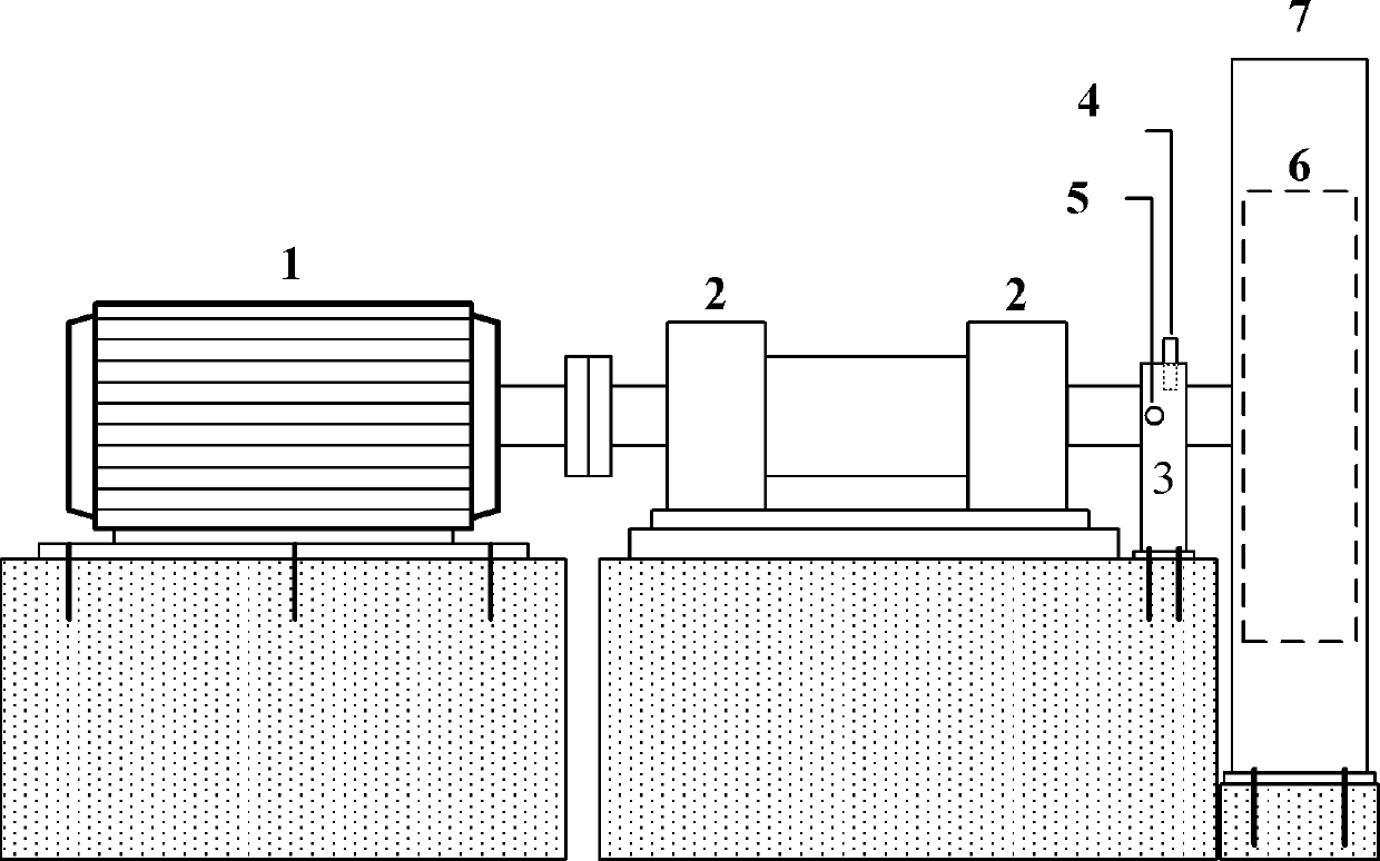
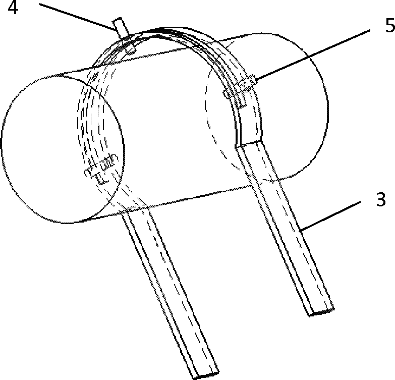
[0045] figure 1 , figure 2 Among them, a fan casing 7 is arranged outside the impeller 6, and the impeller shaft of the impeller 6 is connected with the motor 1 through a bearing 2. Set the bracket 3 on the impeller shaft, install a key phase probe 5 at the horizontal position of the bracket 3, open a groove structure on the side of the key phase probe 5 on the bracket 3 along the circumference, and slide and install two measuring axes in the groove structure Shaft vibration probe 4. The two axial vibration probes 4 are arranged in a horizontal direction and a vertical direction, or arranged at an angle of 45° left and right.

[0046] Dynamic balancing method of the present invention is:

[0047] Step 1. Use the shaft vibration probe 4 and the key phase probe 5 to directly read the vibration value, including power frequency amplitude and phase angl...


PUM


Abstract

The invention discloses a field dynamic balance measuring device and method for a utility boiler side fan. The method comprises the following steps of: I, reading a vibration value by using an axis vibration probe and a key phase value, wherein the vibration value comprises a power frequency amplitude and a phase angle; II, determining a weighting testing position: directly calculating a position required to be weighted by using a read-out phase angle, and calculating a weighting position angle theta according to a formula (1), wherein a position on a key phase groove where a disk rotor is reversely rotated by the angle theta serves as the position required to be weighted; and III, determining a weighting testing magnitude: inquiring needed parameters in a formula (2) from fan specifications to calculate the weighing testing magnitude. Due to the adoption of the device and the method, the successful rate of one-time weighing is greatly increased, a calculating formula is simplified, and complex steps for attaching cursors by halting are reduced on the aspect of process.

Description

technical field [0001] The invention relates to an on-site dynamic balance measuring device and a dynamic balance method for a boiler side fan of a power plant. Background technique [0002] Boiler side fans in power plants include primary fans, powder exhaust fans, induced draft fans, supply fans, desulfurization booster fans, sealing fans, purification fans, etc. They are one of the more important equipment in boiler auxiliary equipment, and the stability of fan operation is directly related to To the safe and normal operation of the entire boiler system. [0003] The mass imbalance of the fan impeller means that the center of mass of the impeller does not coincide with its center of rotation, and it is one of the most common failures of boiler-related fans in power plants. The reasons for the imbalance of the impeller quality are: 1. Congenital defects: such as uneven material, unreasonable structural design, manufacturing and installation errors, that is, there is a cer...

Claims


Application Information

Patent Timeline
IPC IPC(8): G01M1/38
Inventor 郭盈王学同李福尚
Owner ELECTRIC POWER RESEARCH INSTITUTE OF STATE GRID SHANDONG ELECTRIC POWER COMPANY
Why Eureka
Try Eureka