Self-adaptive tracking loop and implementation method

An adaptive tracking and loop technology, applied in the field of navigation, can solve problems such as the small working range of the phase detector and the inability to track satellite signals normally, and achieve the effect of enhancing the tracking ability and improving the adaptability.

Inactive Publication Date: 2012-07-04
BEIHANG UNIV
View PDF2 Cites 51 Cited by
  • Summary
  • Abstract
  • Description
  • Claims
  • Application Information

AI Technical Summary

Problems solved by technology

[0006] The purpose of the present invention is to solve the problem that the existing GPS receiver tracking loop cannot normally track satellite signals in complex and variable environments such as high dynamics and strong interference, and provides an adaptive tracking loop and its implementation method. The unique UKF filter replaces the phase detector and low-pass filter in the traditional carrier loop, directly estimates the carrier phase and carrier frequency and can effectively filter out noise signals, which not only overcomes the shortcoming of the phase detector's small working range, but also eliminates the It eliminates the contradiction between thermal noise and vibration and dynamic stress error, and effectively improves the tracking performance of the tracking loop in complex and variable environments such as high dynamics and strong interference

Method used


Image

  • Self-adaptive tracking loop and implementation method
  • Self-adaptive tracking loop and implementation method
  • Self-adaptive tracking loop and implementation method

Examples


Embodiment Construction

[0044] The present invention will be described in detail below in conjunction with the accompanying drawings.

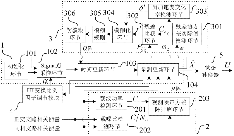
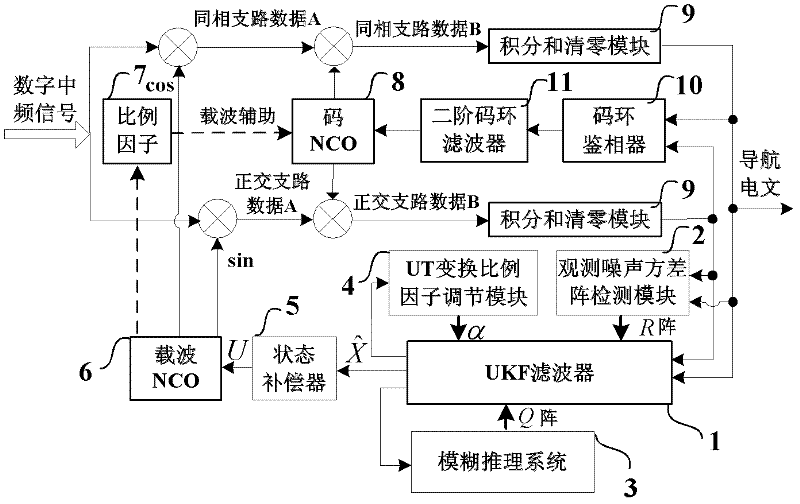
[0045] A novel adaptive tracking loop suitable for high dynamic and strong interference environment of the present invention, such as figure 1 As shown, it includes UKF filter 1, observation noise variance matrix detection module 2, fuzzy reasoning system 3, UT transformation scale factor adjustment module 4, state compensator 5, carrier NCO (numerically controlled oscillator) 6, scale factor 7, code NCO8 , an integrating and clearing module 9, a code loop phase detector 10 and a second-order code loop filter 11.

[0046] On the basis of the traditional tracking loop, the present invention uses the UKF filter 1 to replace the phase detector and low-pass filter in the traditional carrier loop, and designs the observation noise variance matrix detection module 2, fuzzy reasoning system 3, UT Transform the scale factor adjustment module 4 and the state compensator 5; a...


PUM


Abstract

The invention discloses a self-adaptive tracking loop, which comprises an unscented Kalman filter (UKF), an observation noise variance matrix detection module, a fuzzy inference system, an unscented transformation (UT) scale factor regulation module, a state compensator, a carrier wave numerical controlled oscillator (NCO), scale factors, a code NCO, an integration and zero-clearing module, a code loop phase discriminator and a second order code loop filter, and additionally discloses an implementation method for the self-adaptive tracking loop. The implementation method comprises a step 1 ofsignal correlation, integration and zero clearing; a step 2 of code phase tracking; a step 3 of UKF modeling; a step 4 of observation noise variance matrix estimation; a step 5 of process noise variance matrix estimation; a step 6 of UT scale factor regulation; a step 7 of state estimation deviation compensation; and a step 8 of assistance of the carrier wave NCO in the code NCO. According to theself-adaptive tracking loop, the UKF, the observation noise variance matrix detection module and the fuzzy inference system are designed in the carrier tracking loop, so not only can a contradiction between thermal noise vibration in the tracking loop and a dynamic stress error be solved, but a process noise variance matrix and an observation noise variance matrix can be regulated in a self-adaptive manner according to changes of the external environment, and thereby the self-adaptive ability of the tracking loop under complex changeable environments of high dynamic, strong interference, and the like is effectively improved.

Description

technical field [0001] The invention belongs to the technical field of navigation, and relates to an adaptive tracking loop and a realization method. Background technique [0002] The GPS system can provide accurate PVT information (position, speed, time) around the world around the clock, and has very broad uses and development prospects in military and civilian fields. GPS receivers can not only be used for precise guidance of weapons such as ballistic missiles, cruise navigation, over-the-horizon air-to-air missiles, guided bombs, and artillery shells, but also play an important role in manned spaceflight, reentry vehicles, and space exploration. [0003] In the above application fields, GPS receivers usually work in complex and changeable environments such as high dynamics and strong interference, which will cause the following problems for the receiver to track GPS signals: (1) The high dynamic characteristics of the carrier make the GPS carrier generate relatively Lar...

Claims


Application Information

Patent Timeline
Patent Type & Authority Applications(China)
IPC IPC(8): G01S19/29G01S19/30
Inventor 王新龙宋帅
Owner BEIHANG UNIV
Why Eureka
Try Eureka