Optical system of helmet displayer

A helmet-mounted display and optical system technology, applied in the field of optical systems, can solve the problems of difficult movement of optical components, increased processing costs, and complicated assembly processes, and achieve easy fixing and bonding, reduced processing costs, and a large adjustment range Effect

Inactive Publication Date: 2012-07-04
中航华东光电有限公司
View PDF8 Cites 31 Cited by
  • Summary
  • Abstract
  • Description
  • Claims
  • Application Information

AI Technical Summary

Problems solved by technology

Although the light energy entering the human eye 55 is improved under the same circumstances, its free-form surface prism 2 greatly increases the processing cost and reduces its reliability.
[0007] Moreover, in the above two structures, there are three optical elements or optical components. Therefore, after the processing is completed, three parts need to be assembled, and the assembly process is more complicated.
[0008] In addition, because the display source (microdisplay 41 and image information display source 1) is relatively close to the optical assembly (optical element group 43 and combined prism 17), usually only 20 to 30mm, so when adjusting, the distance between the display source and the The movement of optical elements (positive lens 42 and free-form surface prism 2) between optical components is very difficult

Method used


Image

  • Optical system of helmet displayer
  • Optical system of helmet displayer
  • Optical system of helmet displayer

Examples


Embodiment Construction

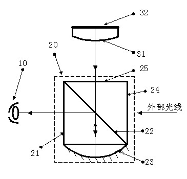
[0036] see figure 1 , the optical system of a head-mounted display in the present invention includes a microdisplay 32 , a glued mirror 31 and an optical combiner 20 . The microdisplay 32 and the glued mirror 31 are glued together as a whole.

[0037]The optical axis is perpendicular to the pixel surface of the microdisplay 32 and passes through its center. The micro-display 32 is a high-brightness, high-resolution micro-display.

[0038] The cemented mirror 31 is a plano-convex lens, the flat side is cemented with the microdisplay 32 and is perpendicular to the optical axis, and the convex side is spherical.

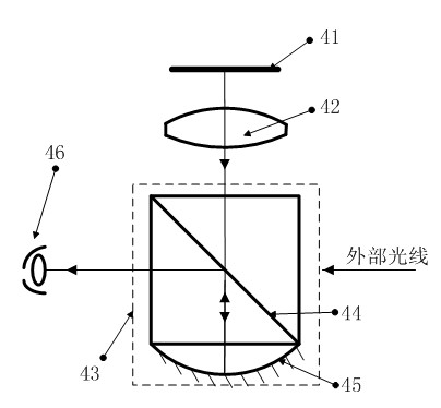
[0039] The optical combiner 20 comprises two rectangular prisms with an angle of 45 degrees and a concave mirror, wherein the optical surface 25 close to the doubled mirror 31, the optical surface 21 close to the pupil 10 of the human eye, and the optical surface 24 close to the external light are all planes , and are perpendicular to the optical axis. The narrow-b...


PUM

PropertyMeasurementUnit
diameteraaaaaaaaaa
wavelengthaaaaaaaaaa
luminanceaaaaaaaaaa

Abstract

An optical system of a helmet displayer comprises a micro displayer, a bonding lens and an optical combiner. The micro displayer and the bonding lens are bonded integrally, the optical combiner comprises two tightly-adhered right-angle prisms forming a 45-degree angle and a concave-surface reflecting mirror, a narrow-band high-reflective optical surface is located at the bonding position of the two right-angle prisms and forms a 45-degree angle respectively with the horizontal optical axis and the vertical optical axis, the concave-surface reflecting mirror and the right-angle prisms are bonded integrally, and the concave surface is the high-reflective optical surface. Light beams are emitted from the micro displayer, are converged through the bonding lens, enter the optical combiner and pass through the narrow-band high-reflective optical surface, then transmitted light beams are converged through the high-reflective optical surface again, and reflected light beams become parallel light beams after the light beams pass through the narrow-band high-reflective optical surface again. An exit pupil is located at the position of a pupil of one human eye, extraneous light enters the optical combiner and passes through the narrow-band high-reflective optical surface, and then the transmitted light beams enter the pupil of one human eye. The optical system of the helmet displayer has the advantages of being compact in system, convenient to correct, good in aberration correction and high in reliability.

Description

technical field [0001] The invention belongs to an optical system, in particular to an optical system applied to a helmet display system, which can be applied to military and civilian helmets. technical background [0002] Head Mounted Display (HMD, Head Mounted Display) is divided into half-projection type and full-projection type, and is an emerging airborne display / aiming system. It can transform the image produced by a small two-dimensional display into a virtual image in front of the human eye through an optical system. Specifically, the light emitted by the small two-dimensional display passes through the lens group to cause the image to produce a similar distant effect due to refraction or diffraction. This effect is used to magnify nearby objects for distant observation or aiming to achieve so-called holographic vision. [0003] In 1968, the world's first real helmet-mounted display was a military helmet-mounted display, that is, the "Sword of Damocles" helmet-mount...

Claims


Application Information

Patent Timeline
Patent Type & Authority Applications(China)
IPC IPC(8): G02B27/01G02B27/10G02B27/00G02B1/04
Inventor 蓝景恒杨新军陈国胜谢松林康涛
Owner 中航华东光电有限公司
Why Eureka
Try Eureka