
Multiplex JTAG (Joint Test Action Group) interface-based FPGA (Field Programmable Gate Array) on-chip logic analyzer system and method

A logic analyzer and interface technology, which is applied in the direction of logic operation inspection and faulty computer hardware detection, can solve the problems of complex communication interface and large memory resources, and achieve the effect of reducing the number of output pins and reducing demand

Active Publication Date: 2012-07-04
INST OF ELECTRONICS CHINESE ACAD OF SCI
View PDF10 Cites 38 Cited by
  • Summary
  • Abstract
  • Description
  • Claims
  • Application Information

AI Technical Summary

Problems solved by technology

[0013] The object of the present invention is to provide a kind of logic analyzer system and method in the FPGA chip of multiplexing JTAG interface, this system is through multiplexing Field Programmable Gate Array (FPGA) internal Joint Test Action Group (JTAG) interface and online setting sampling The method of selecting registers is used to overcome the shortcomings of using too many on-chip memory resources and complex communication interfaces in the prior art, and at the same time, a method of time-sharing transmission of sampling data and trigger status information using the Joint Test Action Group (JTAG) interface is proposed protocol to improve the debugging efficiency and reliability of the field programmable gate array (FPGA) on-chip logic analyzer

Method used


Image

  • Multiplex JTAG (Joint Test Action Group) interface-based FPGA (Field Programmable Gate Array) on-chip logic analyzer system and method
  • Multiplex JTAG (Joint Test Action Group) interface-based FPGA (Field Programmable Gate Array) on-chip logic analyzer system and method
  • Multiplex JTAG (Joint Test Action Group) interface-based FPGA (Field Programmable Gate Array) on-chip logic analyzer system and method

Examples


Embodiment Construction

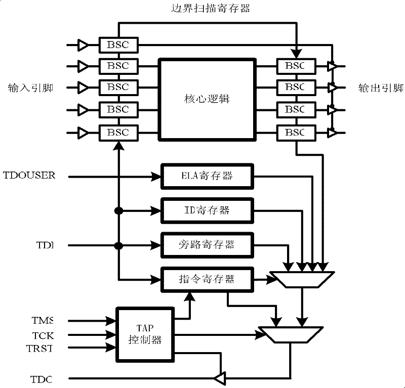
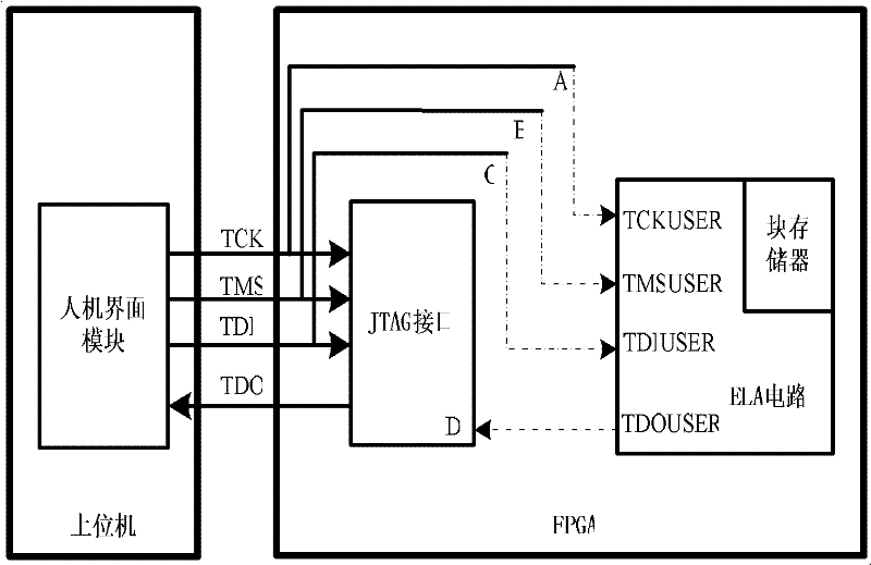
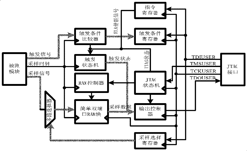
[0058] The core of a field-programmable gate array (FPGA) on-chip logic analyzer system that multiplexes the Joint Test Action Group (JTAG) interface of the present invention is to realize the Joint Test Action Group (JTAG) interface by increasing instructions and wiring constraints The multiplexing of the sampling signal is selected by using the online setting sampling selection register to reduce the demand for on-chip memory resources, and a simple and reliable data transmission protocol is designed to observe the sampling data and trigger status at the same time.

[0059] In order to enable those skilled in the art to better understand the solutions of the present invention, the present invention will be further described in detail below in conjunction with the accompanying drawings and embodiments.

[0060] Such as figure 1 Shown, a kind of Field Programmable Gate Array (FPGA) on-chip logic analyzer system of the multiplexing Joint Test Action Group (JTAG) interface of th...


PUM


Abstract

The invention discloses a multiplex JTAG (Joint Test Action Group) interface-based FPGA (Field Programmable Gate Array) on-chip logic analyzer system and method, which relate to field programmable gate array technology, are used for realizing debug and observation of an internal signal of an FPGA, and mainly comprise a multiplex JTAG interface, an on-chip logic analyzer circuit and a human-computer interface module, wherein the on-chip logic analyzer circuit can be used for selecting different sampling signals on line; and the human-computer interface module is used for receiving sampling signals and triggering states simultaneously. The multiplex JTAG interface-based FPGA on-chip logic analyzer system and method have the beneficial effects that: a method for utilizing the multiplex JTAG interface to realize the on-chip logic analyzer system is provided, and the sampling signals are selected on line, so that the requirement of the on-chip logic analyzer system for on-chip sampling storage resources is reduced, wherein the required storage resource quantity is inversely proportional to the number of sampling signal groups; and a method capable of realizing time division transmission of the sampling signals and triggering state information of JTAG is provided, so that the efficiency for debugging the FPGA is improved.

Description

technical field [0001] The present invention relates to Field Programmable Gate Array (FPGA) technical field, relate in particular to embedded debug system multiplexing Field Programmable Gate Array (FPGA) Internal Joint Test Action Group (JTAG) interface and online setting register, to realize the field programmable A method for observing internal signals of a gate array (FPGA). Background technique [0002] In the process of verifying an IC design using hardware logic such as a field programmable gate array (FPGA), a logic analyzer is usually required to observe the internal signals of the hardware logic. A verification method is similar to the SignalTap tool launched by Altera, which generates configuration files through logic synthesis and wiring together with these function codes and tested codes, and downloads them to hardware logic such as Field Programmable Gate Array (FPGA), and then during the test process The signal is sampled and transmitted to the host computer...

Claims


Application Information

Patent Timeline
IPC IPC(8): G06F11/25
Inventor 谭宜涛杨海钢
Owner INST OF ELECTRONICS CHINESE ACAD OF SCI
Learn More