Control method applicable to resistance changing memory resistor of nerve cell circuit

A technology of resistive memristor and control method, which is applied in the field of neuron circuits, can solve the problems of not being too small, restricting large-scale integration, complex peripheral circuits, etc., and achieves precise control of resistance floating, which is conducive to large-scale integration , fast and precise adjustment effect

Active Publication Date: 2012-07-04
PEKING UNIV
View PDF2 Cites 34 Cited by
  • Summary
  • Abstract
  • Description
  • Claims
  • Application Information

AI Technical Summary

Problems solved by technology

By adjusting the reset terminal voltage, the resistance value of the resistive memristor can be variable, but the peripheral circuit of this method is very complicated
By adjusting the current of the resistive memristor, the change of the resistance value of the resistive memristor can be controlled. The existing methods mainly include controlling the setting current and connecting metal oxide semiconductor MOS transistors in series. The peripheral circuit complexity of the former is relatively high. In the method of connecting MOS transistors in series, due to the large reverse current through the MOS transistors, the area cannot be too small, which limits its large-scale integration capability.
In addition, none of the above three methods can accurately adjust the resistance fluctuation caused by the unstable factors of the resistive memristor itself.

Method used


Image

  • Control method applicable to resistance changing memory resistor of nerve cell circuit
  • Control method applicable to resistance changing memory resistor of nerve cell circuit
  • Control method applicable to resistance changing memory resistor of nerve cell circuit

Examples


Embodiment Construction

[0017] The present invention will be further described through the embodiments below in conjunction with the accompanying drawings.

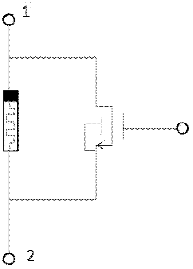
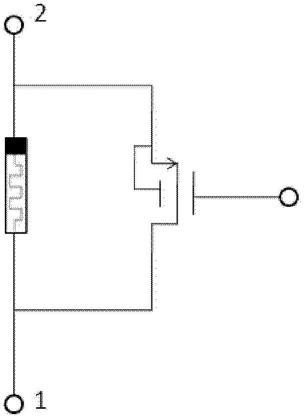
[0018] figure 1 is a schematic diagram of a parallel structure of a bipolar resistive memristor and an NMOS transistor, figure 2 It is a schematic diagram of a parallel structure of a bipolar resistive memristor and a PMOS transistor. In the figure, 1 is the drain terminal of the MOS transistor; 2 is the source terminal of the MOS transistor.

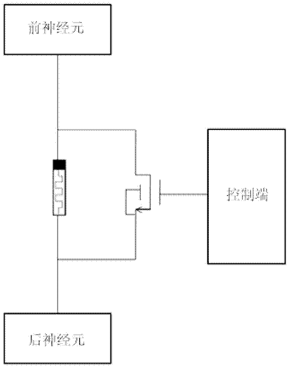
[0019] Taking the NMOS transistor as an example, the parallel structure of the bipolar resistive memristor and the NMOS transistor is connected in the neuron circuit, the positive terminal of the resistive memristor is connected to the drain terminal of the NMOS transistor, and the negative terminal is connected to the source terminal of the NMOS transistor. The drain terminal of the NMOS transistor is connected to the front neuron, the source terminal is connected to the rear neuron, and the gate termi...


PUM


Abstract

The invention discloses a control method applicable to a resistance changing memory resistor of a nerve cell circuit. According to the control method disclosed by the invention, two ports of a resistance changing memory resistor are respectively connected with a drain terminal and a source terminal of an MOS (metal oxide semiconductor) transistor, a parallel connection structure is formed, the parallel connection structure is respectively connected with a front nerve cell and a rear nerve cell, and a gate voltage is added on a gate terminal of the MOS transistor. according to the invention, the resistance changing memory resistor is connected with the MOS transistor in parallel, in a study state, the resistance changing memory resistor is set to a preset resistance value by adjusting the gate voltage of the MOS transistor; and in a calculation state, channel resistance of the MOS transistor is controlled by virtue of the gate voltage, thus resistance value of the parallel connection structure of the resistance changing memory resistor and the MOS transistor is accurately controlled, and the resistance of the parallel connection structure is rapidly and accurately adjusted. Area of the MOS transistor can be small, thus being beneficial to large-scale integration; meanwhile, the gate voltage of the MOS transistor is controlled, change of the resistance of the resistance changing memory resistor can be realized, and resistance floating can be accurately controlled.

Description

technical field [0001] The invention relates to a neuron circuit, in particular to a control method suitable for a resistance variable memristor used as a synaptic connection in a neuron circuit. Background technique [0002] In the continuous development of the information society, people have more and more requirements for large-scale and intelligent computing. Neural computing is a large-scale, parallel, and intelligent computing model, and intelligent robots based on it have great application prospects in the future. [0003] The neuron circuit used for neural computing is divided into two working states: one is the learning state, which is used to set the weight of synaptic connections; the other is the calculation state, which is used for circuit calculation. A large number of synaptic connections are required in neuronal circuits, and these synaptic connections must have variable weights and small areas for large-scale integration. For a resistive memristive device ...

Claims


Application Information

Patent Timeline
Patent Type & Authority Applications(China)
IPC IPC(8): G11C11/56
Inventor 黄如杨庚雨张耀凯张丽杰陈诚潘越蔡一茂黄英龙谭胜虎
Owner PEKING UNIV
Why Eureka
Try Eureka