Check patentability & draft patents in minutes with Patsnap Eureka AI!

Excitation supply circuit for synchronous brushless generator

A generator and circuit technology, applied in the direction of synchronous generators, etc., can solve the problems of inconvenient installation and maintenance, difficult manufacturing, large volume, etc., and achieve the effect of improving dynamic performance and increasing application occasions

Inactive Publication Date: 2012-07-04
苏州德丰电机有限公司
View PDF5 Cites 1 Cited by
  • Summary
  • Abstract
  • Description
  • Claims
  • Application Information

AI Technical Summary

Problems solved by technology

However, in some special working conditions, such as engineering applications, starting asynchronous machines, etc., which have special requirements on the dynamic performance of the generator, ordinary brushless generators cannot adapt well, and may even change with the terminal voltage of the generator. Reduced, the automatic voltage regulator loses its function, which causes the generator to lose excitation, and the generator no longer generates power
The usual solution is to increase and change the excitation method, and the commonly used excitation method is a phase compound excitation device with compound excitation characteristics or a permanent magnet generator excitation device with a separate power supply. These devices are large in size, difficult to manufacture, Disadvantages such as inconvenient installation and maintenance and high cost

Method used


Image

  • Excitation supply circuit for synchronous brushless generator
  • Excitation supply circuit for synchronous brushless generator
  • Excitation supply circuit for synchronous brushless generator

Examples


Embodiment 1

[0018] Working process of brushless alternator:

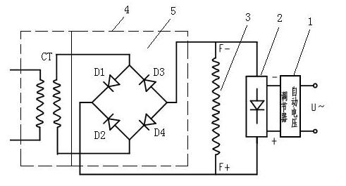
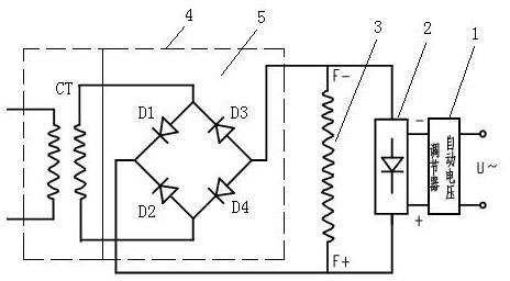
[0019] The brushless alternator is composed of two generators, one is the exciter and the other is the main generator. The field winding of the main generator is on the rotor, the armature winding is on the stator, and the generated electricity is output; the armature winding of the exciter is on the rotor, and the field winding is on the stator. Provide excitation to the excitation winding of the exciter on the stator, and its rotor armature winding will generate alternating current, and after rectification, its rotor will supply power to the excitation winding of the main generator on the rotor, so that the electric current of the main generator on the stator The armature winding induces the required alternating current.

[0020] Such as figure 1 As shown, in the present invention, the input power is adjusted by the automatic voltage regulator 1, and after being rectified by a rectifier circuit 2, excitation is provided to ...

Embodiment 2

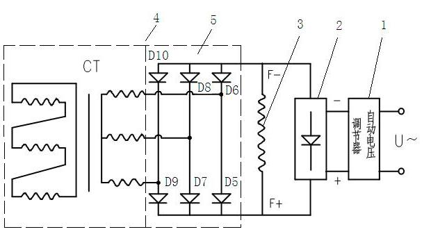
[0026] On the basis of Embodiment 1, the rectifier circuit 5 in this embodiment is a three-phase rectifier bridge circuit. Such as figure 2 As shown, the rectifier circuit 5 includes three rectifier bridge arms, two rectifier diodes are arranged on each bridge arm, and the cathodes of a diode D5, D7, D9 on each bridge arm are connected in common and connected with a certain stator of the excitation winding 3 The anodes of the other diodes D6, D8, D10 on each bridge arm are connected in common and connected with the other stator end of the excitation winding 3, and the anodes of the diodes D5, D7, D9 are respectively connected to the diodes D6, D8, D10 The negative poles are connected in common and connected to the current transformers CT respectively. All the other are identical with embodiment 1.


PUM


Abstract

The invention discloses an excitation supply circuit for a synchronous brushless generator. A load current supply circuit forming positive feedback with load current is connected in parallel with the two ends of a stator of an excitation winding of an exciter, and compensates for an input signal of an input power supply of the exciter. The input signal of the input power supply is regulated by an automatic voltage regulator, and then excites the excitation winding on the stator of the exciter. The automatic voltage regulator and the load current supply circuit provide voltage and current signals for the exciter at the same time, so that the dynamic performance of the generator is greatly improved, the normal supply of the excitation of the generator can be ensured under various service conditions or load variation conditions with high requirements for the dynamic performance, and the application range of the generator can be widened.

Description

technical field [0001] The invention relates to an excitation supply device for a synchronous brushless generator, which belongs to the technical field of motors. Background technique [0002] At present, the excitation power of a general synchronous brushless generator is directly provided by the automatic voltage regulator, and the input power of the automatic voltage regulator comes from the voltage signal of the main engine. Under normal conditions and stable load conditions, the generator can operate normally. , and has good voltage adjustment characteristics, and the steady-state voltage adjustment rate can reach within ±1%. However, in some special working conditions, such as engineering applications, starting asynchronous machines, etc., which have special requirements on the dynamic performance of the generator, ordinary brushless generators cannot adapt well, and may even change with the terminal voltage of the generator. Reduced, the automatic voltage regulator l...

Claims


Application Information

Patent Timeline
IPC IPC(8): H02K19/38
Inventor 李文富高志伟
Owner 苏州德丰电机有限公司
Features
  • R&D
  • Intellectual Property
  • Life Sciences
  • Materials
  • Tech Scout
  • Unparalleled Data Quality
  • Higher Quality Content
  • 60% Fewer Hallucinations
Learn More