Displacement estimating method and suspension control system for bearingless synchronous reluctance motor

A synchronous reluctance motor and bearingless technology, which is applied in the control system, vector control system, motor generator control, etc., can solve the problems of low precision of motor suspension control, observation of torque winding flux linkage, and reduced system reliability.

Active Publication Date: 2012-07-04
江苏扬先科技有限公司
View PDF3 Cites 12 Cited by
  • Summary
  • Abstract
  • Description
  • Claims
  • Application Information

AI Technical Summary

Problems solved by technology

However, installing a mechanical displacement sensor inside the motor will reduce the reliability of the system, increase the hardware complexity of the system and the total system cost
In addition, the establishment of the levitation force equation of the bearingless synchronous reluctance motor is based on the magnitude of the current in the two sets of windings of the motor. When the motor is in levitation control, the flux linkage of the torque winding is not observed, which makes the levitation control accuracy of the motor not high.
[0004] After searching the existing literature and patents, it was found that Zhang Hannian and others applied for the national invention patent (application number: 201010017952.6) of "displacement estimation method of bearingless synchronous reluctance motor, displacement sensorless control method and device", the above method is Injecting a high-frequency signal into the torque winding of the motor realizes sensorless control, but the high-frequency signal injected into the torque winding aggravates the pulsation of the electromagnetic torque and enhances the coupling relationship between the electromagnetic torque and the levitation force

Method used


Image

  • Displacement estimating method and suspension control system for bearingless synchronous reluctance motor
  • Displacement estimating method and suspension control system for bearingless synchronous reluctance motor
  • Displacement estimating method and suspension control system for bearingless synchronous reluctance motor

Examples


Embodiment Construction

[0091] In order to make the content of the present invention more comprehensible, further description will be made below in conjunction with the accompanying drawings and specific embodiments.

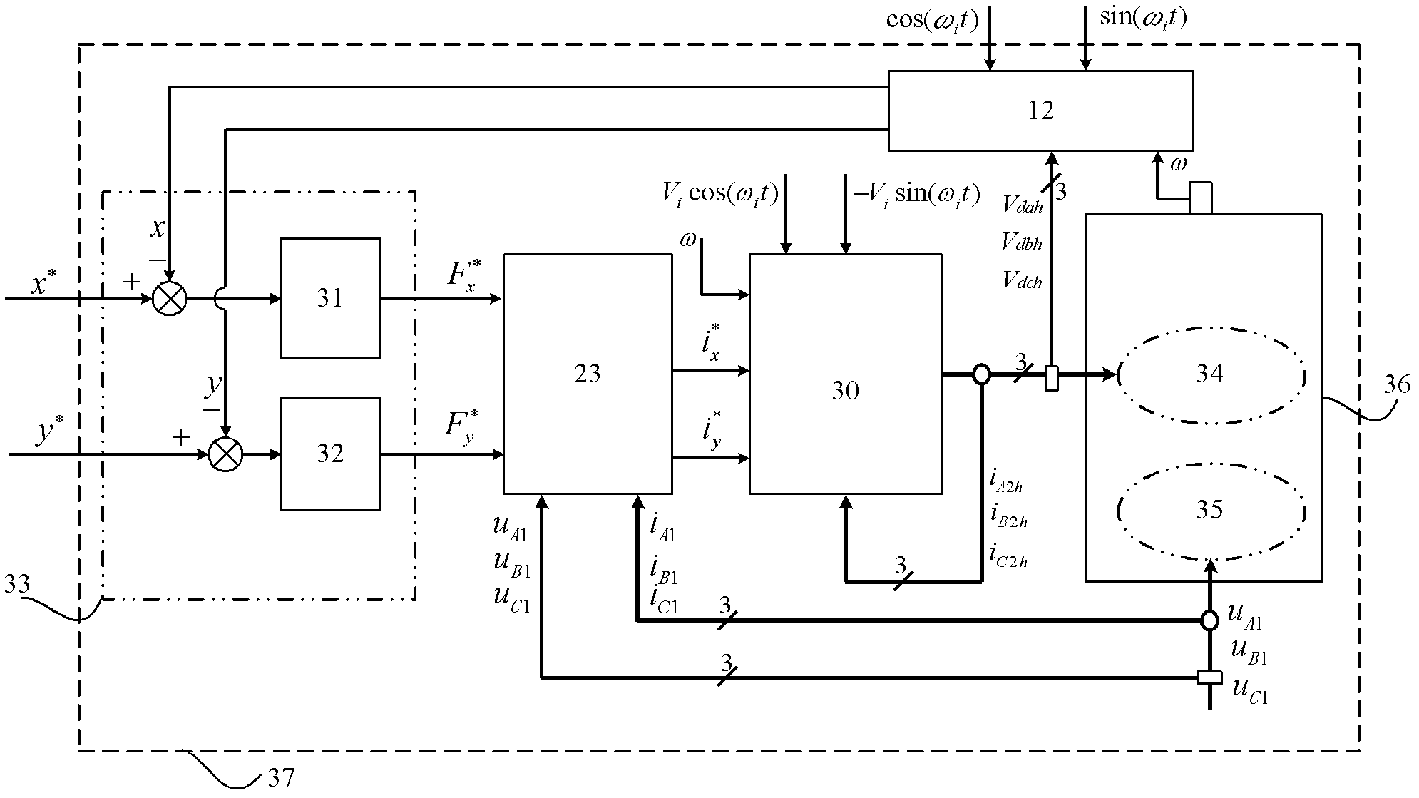
[0092] Such as figure 1 As shown, the bearingless synchronous reluctance motor levitation control system of the present invention includes an extended displacement estimator 12, a closed-loop regulator 33 of rotor radial displacement, an extended levitation force / current modulator 23, and an extended SPWM inverter 30 :

[0093] The closed-loop regulator 33 is composed of two PD regulators 31-32, and the bearingless synchronous reluctance motor 36 includes a suspension winding 34 and a torque winding 35;

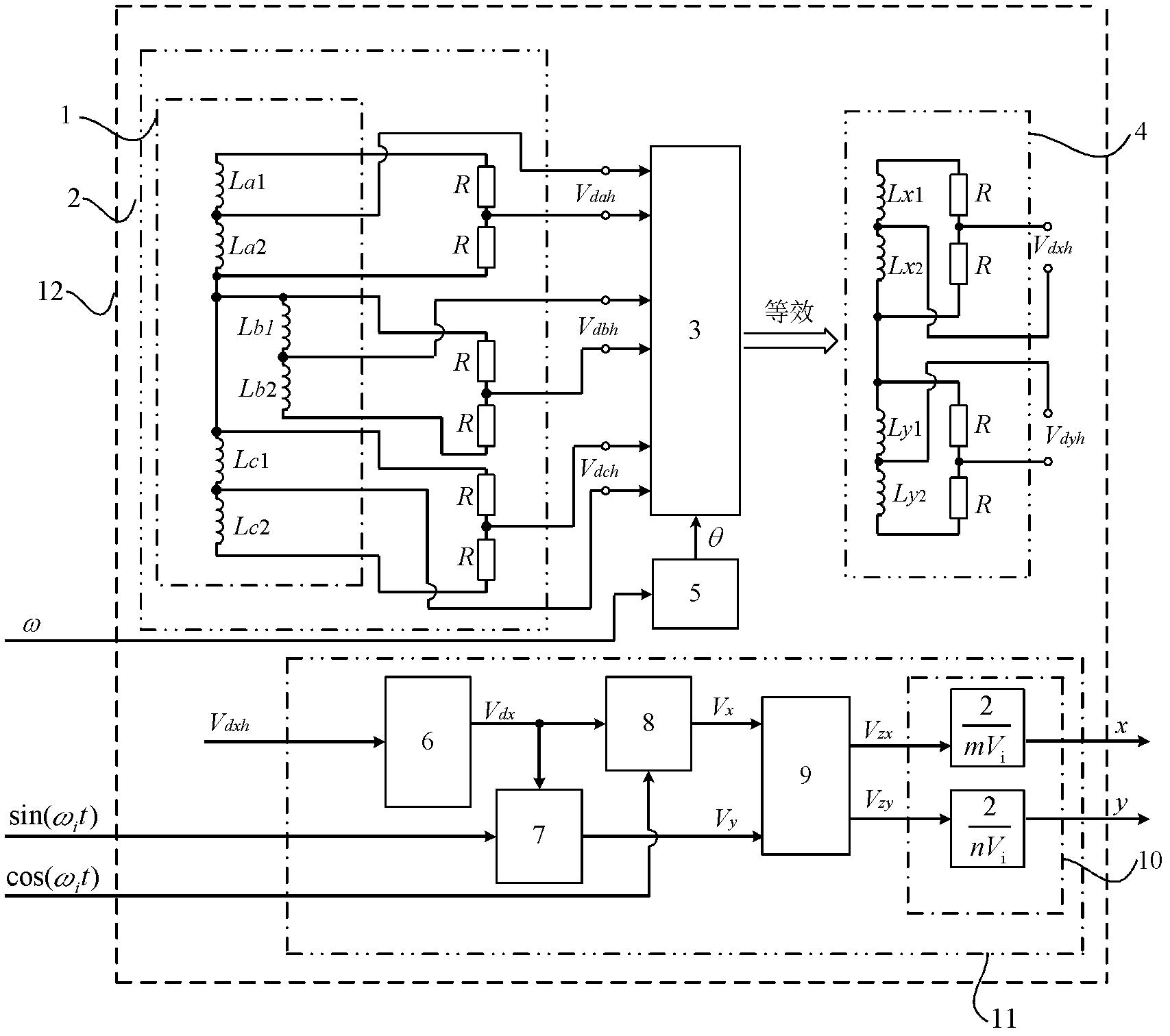
[0094] combine figure 2 , the extended displacement estimator 12 is made up of Cark transform 3, integrator 5, differential voltage detection model 2, and displacement estimator 11; displacement estimator 11 includes: band-pass filter 6, multipliers 7-8; low-pass filter 9. Scale f...


PUM


Abstract

The invention discloses a displacement estimating method and a suspension control system for a bearingless synchronous reluctance motor. When the suspension control system which is constructed on the basis of the displacement estimating method disclosed by the invention is applied, firstly, a two-phase winding differential voltage is acquired and equivalently obtained on the basis of a differential voltage detection model; then a rotor displacement estimated value is obtained by utilizing a displacement estimator; a reference value of a suspension force is output by a closed-loop regulator; an expanded suspension force/current modulator outputs a suspension winding two-phase reference current to an expanded SPWM (Silent Pulse Width Modulation) inverter after operating the suspension force reference value and a torque winding three-phase voltage and current detection value which are used as input signals; and finally, a three-phase suspension winding is supplied with power by utilizing the expanded SPWM inverter, so that the suspension force control can be implemented and meanwhile, a high-frequency voltage signal is provided for estimation of the rotor displacement. According to the invention, not only can the stable suspension of a rotor be implemented, but also the rotor displacement can be accurately estimated and excellent control performance is achieved.

Description

technical field [0001] The invention relates to the technical field of AC motor drive and control, in particular to a high-performance suspension control technology under the condition of a bearingless synchronous reluctance motor without a displacement sensor, and relates to a displacement estimation method and a suspension control system of a bearingless synchronous reluctance motor. Background technique [0002] The bearingless synchronous reluctance motor uses the joint action of the torque winding and the suspension winding in the stator slot to change the distribution of the synthetic air gap magnetic field, thereby controlling the magnitude and direction of the rotational force and suspension force on the rotor, and realizing the speed regulation operation of the motor and stable suspension. Compared with other types of bearingless motors (such as bearingless asynchronous motors, bearingless permanent magnet synchronous motors, and bearingless switched reluctance moto...

Claims


Application Information

Patent Timeline
Patent Type & Authority Applications(China)
IPC IPC(8): H02P6/18H02P21/13H02P21/18
Inventor 张汉年鲍安平孙刚张磊张照锋
Owner 江苏扬先科技有限公司
Why Eureka
Try Eureka