Traveling wave tube linearizer

A technology of linearizer and traveling wave tube, which is applied in the direction of improving amplifiers to reduce nonlinear distortion, etc., can solve the problems of complex structure of power amplifiers and linearization of traveling wave tube amplifiers, and achieve faster debugging, production scheduling, and simple structure , The effect of simple circuit structure

Inactive Publication Date: 2012-07-04
UNIV OF ELECTRONIC SCI & TECH OF CHINA
View PDF7 Cites 10 Cited by
  • Summary
  • Abstract
  • Description
  • Claims
  • Application Information

AI Technical Summary

Problems solved by technology

[0005] The purpose of the present invention is to solve the problem that the existing pre-distortion linearization power amplifier has a compl

Method used


Image

  • Traveling wave tube linearizer
  • Traveling wave tube linearizer
  • Traveling wave tube linearizer

Examples


Embodiment Construction

[0016] The present invention will be further elaborated below in conjunction with the accompanying drawings and specific embodiments.

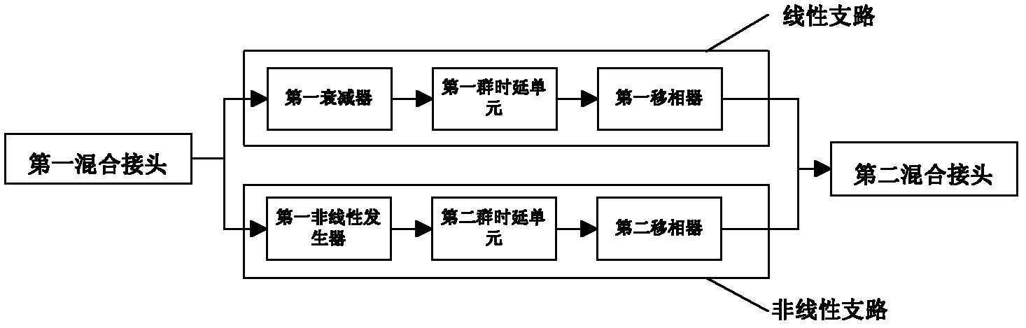
[0017] The structure diagram of the traveling wave tube linearizer of the present invention is as figure 1 As shown, including: the first hybrid connector, the second hybrid connector, the linear branch and the nonlinear branch, the RF input signal is divided into two paths through the first hybrid connector, which are recorded as the first branch signal and the second branch signal , the first branch signal and the second branch signal are respectively input to the linear branch and the nonlinear branch, and the output signals of the linear branch and the nonlinear branch are vector-coupled into a radio frequency output signal through the second hybrid joint.

[0018] Here, the linear branch includes a first attenuator, a first group delay unit and a first phase shifter, and the first branch signal passes through the first attenuator, the fir...


PUM


Abstract

The invention discloses a traveling wave tube linearizer, which comprises a first hybrid junction, a second hybrid junction, a linear branch and a nonlinear branch. A radio frequency input signal is divided into two paths by the first hybrid junction, and the two paths are recorded as a first branch of signals and a second branch of signals. The first and second branches of signals are input into the linear branch and the nonlinear branch respectively. Output signals of the linear branch and the nonlinear branch are coupled into a radio frequency output signal by the second hybrid junction. The traveling wave tube linearizer has a simple structure; and the curve of the linearizer can be regulated by regulating amplitude expansion, phase expansion and the waveform of a nonlinear generator, and then the linearizer is matched with the characteristics of different traveling wave tube power amplifiers to linearize the different traveling wave tube power amplifiers, so that the problems of nonlinear differences among different traveling wave tubes are solved.

Description

technical field [0001] The invention belongs to the technical field of power amplifiers, in particular to a traveling wave tube linearizer. technical background [0002] With the rapid development of mobile communication technology, wireless communication frequency bands are becoming more and more crowded, and spectrum resources are becoming increasingly tight. In order to accommodate more communication channels within a limited spectrum range, some broadband digital transmission technologies (OFDM, WCDMA, etc.) and modulation methods with high spectrum efficiency (M-QAM, etc.). The signals transmitted by these technologies have the characteristics of non-constant envelope, wide frequency band, and peak-to-average ratio. When the modulated signal passes through a nonlinear power amplifier, in-band and out-of-band distortion will occur, resulting in spectral expansion of the output signal and out-of-band distortion. The signal interferes with adjacent channels, and the in-ba...

Claims


Application Information

Patent Timeline
IPC IPC(8): H03F1/32
Inventor 陈长伟秦开宇岳凯
Owner UNIV OF ELECTRONIC SCI & TECH OF CHINA
Why Eureka
Try Eureka