Ion-exchange device, column therefor, and water treatment device

A technology of ion exchange device and water treatment device, which is applied in the direction of ion exchange treatment device, ion exchange water/sewage treatment, ion exchange, etc., can solve the problems of water quality reduction, reduce height, manufacture cheaply, and improve economy Effect

Inactive Publication Date: 2012-07-04
KURITA WATER INDUSTRIES LTD
View PDF7 Cites 2 Cited by
  • Summary
  • Abstract
  • Description
  • Claims
  • Application Information

AI Technical Summary

Problems solved by technology

[0008] In the tower body for the ion exchange device of Patent Document 1, when the raw water is passed through in the order of cation exchange resin → anion exchange resin, a large amount of water from the a

Method used


Image

  • Ion-exchange device, column therefor, and water treatment device
  • Ion-exchange device, column therefor, and water treatment device
  • Ion-exchange device, column therefor, and water treatment device

Examples


Embodiment 1

[0093] Embodiment 1, comparative example 1

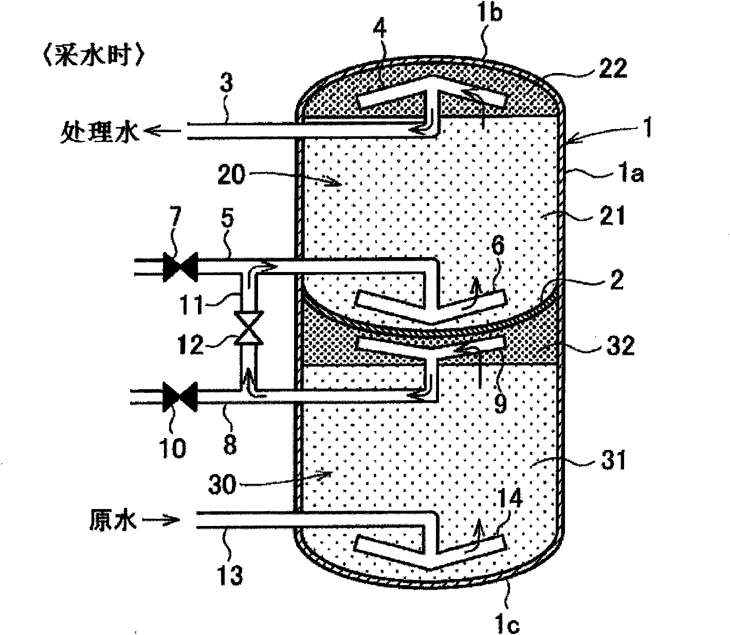
[0094] Used in Example 1 Figure 1a , 1b The ion exchange device shown. The specifications are as follows.

[0095] Tower diameter: 450mm

[0096] Tower height: 3000mm

[0097] Upper chamber volume: 190L

[0098] Lower chamber volume: 260L

[0099] Filling capacity of cation exchange resin 21: 150L

[0100] Filling capacity of anion exchange resin 31: 200L

[0101] Filling amount of non-reactive resin 22: 30L

[0102] Filling amount of non-reactive resin 32: 30L

[0103] In Comparative Example 1, a commercially available mixed-bed ion exchange device was used. The specifications are as follows.

[0104] Tower diameter: 450mm

[0105] Tower height: 4000mm

[0106] Volume: 640L

[0107] Filling capacity of cation exchange resin: 150L

[0108] Filling capacity of anion exchange resin: 200L

[0109] In Example 1 and Comparative Example 1, the following materials were used for the anion exchange resin and the cation exchan...

Embodiment 2

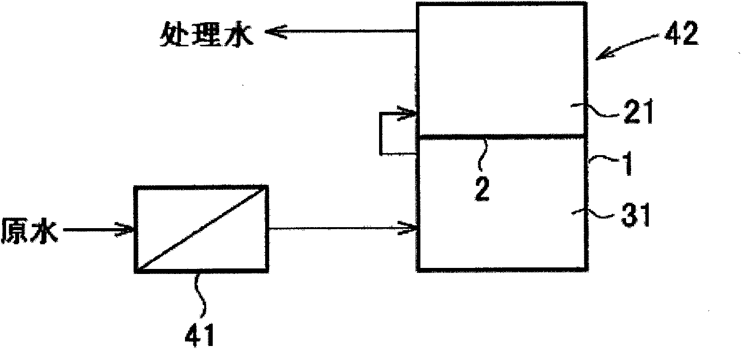
[0132] Pass the simulated raw water described later to the RO device as the hardness component removal equipment, and then pass the water to Figure 1a , 1b The ion exchange device shown. The main conditions of this ion exchange device are as follows.

[0133] (1) Ion exchange resin

[0134] Cation exchange resin: Dow 650C, filling volume 300mL

[0135] Anion exchange resin: Dow 550A, filling volume 600mL

[0136] (2) Water flow: 1L / min

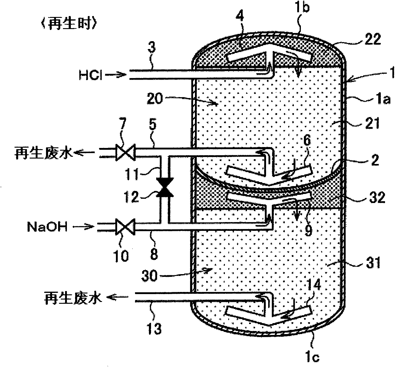
[0137] (3) Regeneration conditions

[0138] The regeneration solution is as follows.

[0139] Aqueous HCl solution: HCl concentration 5% by weight, water flow rate: 1L / h, 30 minutes

[0140] NaOH aqueous solution: NaOH concentration 5% by weight, water flow rate: 2L / h, heating at 40°C for 30 minutes

[0141] The regenerating solution was passed as follows.

[0142] 30 minutes (drug flow time) → 30 minutes ultrapure water flow (drug extrusion time) → 15 minutes raw water flow (operation switching time)

[0143] (4) RO device

[0144]...

reference example 1

[0157] In Example 2, after passing the simulated raw water through the RO device, the water was first passed through the cation exchange resin, and then the water was passed through the anion exchange resin. That is, the order of passing water through the anion exchange resin and the cation exchange resin is reversed from Example 2. Other than that, water was passed in the same manner as in Example 2. As a result, as shown in Table 4, the Na concentration in the treated water after 1 hour (Hr) of water flow after regeneration was 3 ppt, which was confirmed to be a concentration several times higher than in Example 2. The Na concentration of the treated water between 360 hours after the start of water flow is shown in image 3 .


PUM

PropertyMeasurementUnit
Diameteraaaaaaaaaa

Abstract

Provided is an ion-exchange device including a column in which an anion-exchange resin and a cation-exchange resin are prevented, without fail, from being reversely regenerated. With the device, it is possible to produce high-quality deionized water even immediately after regeneration. Also provided is a column for the device. During regeneration, a valve (12) is closed and valves (7, 10) are opened, and a solution of an acid such as HCl is supplied through upper supply/discharge piping (3), while a solution of an alkali such as NaOH is supplied through third connecting piping (8). The acid solution flows through a water collection/distribution member (4), an inert resin (22), a cation-exchange resin (21), a water collection/distribution member (6), connecting piping (5), and the valve (7) in this order to regenerate the cation-exchange resin (21). The alkali solution flows through a water collection/distribution member (9), an inert resin (32), an anion-exchange resin (31), a water collection/distribution member (14), and lower supply/discharge piping (13) in this order to regenerate the anion-exchange resin (31).

Description

technical field [0001] The invention relates to a regenerative ion exchange device and a tower body used therefor, which includes an anion exchange resin and a cation exchange resin. The invention also relates to a water treatment device comprising the ion exchange device. Background technique [0002] Ion exchange devices are widely used in pure water or ultrapure water manufacturing equipment and the like in the electronics industry and the like. As one of such ion exchange devices, a mixed-bed ion exchange device is known. [0003] A mixed-bed ion exchange device, including an ion exchange tower having a mixed ion exchange resin layer mixed with a strongly acidic cation exchange resin and a strongly basic anion exchange resin, for example, through the downflow of raw water in the ion exchange tower The cations and anions in the raw water are ion-exchanged at the same time to produce pure water with high purity. Next, in the same tower when each ion exchange resin is be...

Claims


Application Information

Patent Timeline
IPC IPC(8): C02F1/42B01J47/02B01J49/00B01J49/90
CPCC02F2001/422C02F2001/425C02F1/42B01J47/028C02F2303/16B01J49/0017B01J49/08
Inventor 岩崎守石塚谕竹山一宫崎洋一福井长雄北见胜信
Owner KURITA WATER INDUSTRIES LTD
Why Eureka
Try Eureka