Co-rotating type cooling drum

A cooling drum and co-rotating technology, which is applied in casting molding equipment, cleaning/processing machinery of casting mold materials, metal processing equipment, etc., can solve the difficulty of replacing and maintaining the spiral sheet 5, small heat exchange area, and slow heat exchange speed and other problems, to achieve the effect of long service life, large area and fast cooling speed

Inactive Publication Date: 2012-07-11
姜海林 +2
View PDF7 Cites 7 Cited by
  • Summary
  • Abstract
  • Description
  • Claims
  • Application Information

AI Technical Summary

Problems solved by technology

When working, the deceleration motor 15 drives the active rubber wheel 14 to rotate the friction transmission cylinder 6 to rotate, and the water pump pumps water to the spray water valve 8 to spray the cylinder 6 to cool down. The high-temperature sand enters from the sand inlet 1 at one end of the cylinder 6. Under the action of the reduction motor 15, the active rubber wheel 14 is driven to rub the barrel 6 to rotate. The high-temperature sand moves along the spiral plate 5 in the barrel 6. Water is sprayed on the top of the barrel 6 to cool down the barrel 6 for heat exchange. The sand flows from the other side. One end of the sand outlet 10 flows out. Its heat exchange method is that the high-temperature hot sand dynamically contacts the inner surface of the cylinder and realizes heat exchange with the water outside the cylinder, thereby achieving the purpose of cooling. There are the following disadvantages in using this device for cooling: 1. Hot sand sand The layer is thick, the heat exchange area is small, and the heat exchange speed is slow; 2. The movement of the hot sand with a large diameter of the cylinder body 6 cannot be rolled and rubbed smoothly, and the heat exchange is slow, which is prone to friction and wear. It is difficult to replace and maintain the cylinder body 6 and the spiral piece 5 Low productivity and short service life

Method used


Image

  • Co-rotating type cooling drum
  • Co-rotating type cooling drum
  • Co-rotating type cooling drum

Examples


Embodiment 1

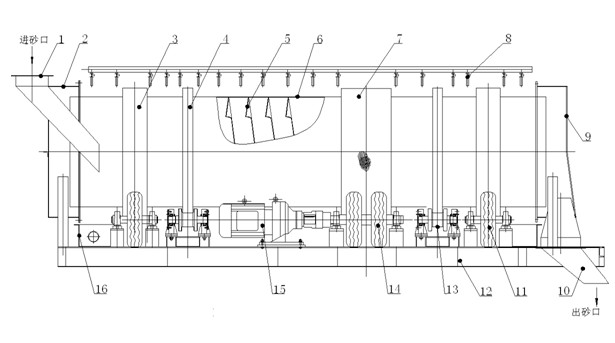
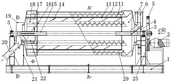
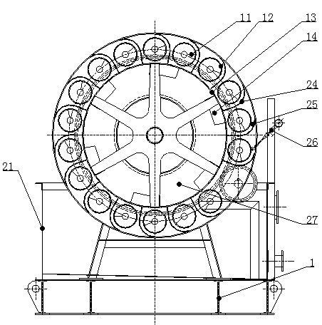
[0024] A co-rotating cooling drum, which consists of three parts: a power transmission system installed on the base 1, a drum driven by the power transmission system, and a cooling device. The two ends of the rotating drum are respectively connected with a feeding device and a discharging device . The power transmission system includes a reduction motor 2 erected on the base 1. The reduction motor 2 transmits torque through the driving gear 23 and the driven gear 5 of the meshing transmission to the shaft 15 supported by the bearing 3 at both ends and passing through the inside of the drum. 15 drives the drum to work. The drum includes a horizontally installed inner cylinder 13, several outer cylinders 12 surrounding the outer periphery of the inner cylinder 13, and a sand inlet chamber 7 and a sand outlet chamber 18 respectively connected to the feeding device and the discharging device. The junction between 13 and shaft 15 is a fixed and sealed connection, and the joints be...


PUM


Abstract

The invention relates to a co-rotating type cooling drum, which is specially suitable for fast cooling of high-temperature sands in casting industry and belongs to the technical field of cooling device structures. The co-rotating type cooling drum is characterized by being formed by a power transmission system installed on a base, a drum driven by the power transmission system and a cooling device. A feeding device and a discharging device are respectively connected at two ends of the drum. The co-rotating type cooling drum is reasonable in design, and due to contact between hot sand and inner wall of an outer tube and cooling media filled outside the outer tube, the hot sand in the outer tube moves to a sand cavity in rolling mode and exchanges heat with the cooling media water outside the outer tube. Due to the fact that one screw pitch can be moved in rolling mode when the hot sand in a spiral groove of the outer tube turns for one round, the longer the cooling time is, the better the cooling effect is, and area of cooling water is large. Therefore, cooling is fast. Further, rotating speed of the hot sand can be controlled by a frequency converter according to cooling conditions, maintenance is convenient, service life is long, yield is high, power consumption is low, electricity is saved and the co-rotating type cooling drum has wide application prospect.

Description

[0001] technical field [0002] The invention relates to a co-rotating cooling drum, which is especially suitable for rapid cooling of high-temperature sand with a large specific gravity in the foundry industry, and belongs to the technical field of cooling device structures. Background technique [0003] At present, in the foundry industry, a horizontal drum cooler is used to cool high-temperature sand, such as figure 1 As shown, the cylinder body 6 is included, and the bottom base 12 of the cylinder body 6 is provided with a supporting rubber wheel 11, a cylinder body support wheel 13 and a water receiving tank 16, a spiral piece 5 is arranged in the cylinder body 6, and two ends of the cylinder body 6 are respectively set into The sand shield 2 and the sand outlet shield 9 are respectively provided with a sand inlet 1 and a sand outlet 10 on the shield. The outer wall of the cylinder 6 is provided with support rings 3, 4 and an active friction ring 7, and the base 12 is i...

Claims


Application Information

Patent Timeline
Patent Type & Authority Applications(China)
IPC IPC(8): B22C5/08
Inventor 姜海林
Owner 姜海林
Why Eureka
Try Eureka