
Robot claw

A technology of robots and grippers, applied in the directions of manipulators, chucks, manufacturing tools, etc., can solve the problems of overloading, detachment, and bulkiness of reclaiming materials, and achieve the effect of good use effect, light use weight and prolong life.

Inactive Publication Date: 2015-06-03
安徽果力智能科技股份有限公司
View PDF8 Cites 0 Cited by
  • Summary
  • Abstract
  • Description
  • Claims
  • Application Information

AI Technical Summary

Problems solved by technology

[0002] The robot grippers circulating in the market are generally only suitable for routine automated production operations. When high-end mobile phone manufacturing industries require high-precision processing or need to grab some structurally complex parts, they are cumbersome and cannot meet the processing requirements.
Taking a robot with a load of 5 kg commonly used in the mobile phone industry as an example, its robot gripper has the following defects: 1. The weight of the robot gripper itself is large, and the weight of the grasped object can easily exceed the theoretical tolerance value of the robot ;2. The positioning pins on the lower surface of the cylinder block cannot be freely set and edited according to the needs; 3. When the friction force between the positioning holes on the object to be grasped and the positioning pins on the processing machine is too large, the robot will overload the material. The robot claw itself cannot separate the positioning hole on the jig or the grasped object from the positioning pin on the processing machine; 4. The post-editing of the cylinder block is highly restrictive, and even cannot be edited, etc.

Method used


Image

  • Robot claw
  • Robot claw
  • Robot claw

Examples


Embodiment Construction

[0018] In order to describe the technical content, structural features, achieved goals and effects of the present invention in detail, the following will be described in detail in conjunction with the embodiments and accompanying drawings.

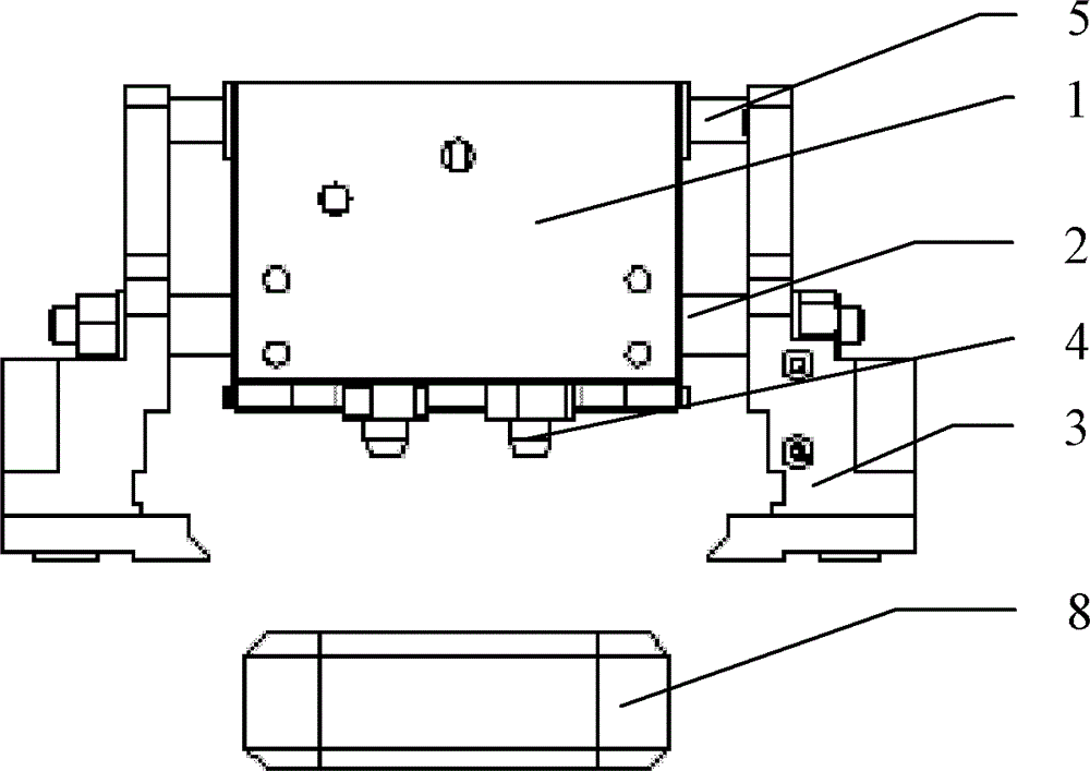
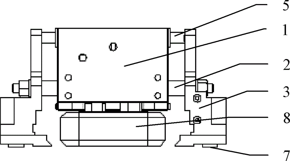
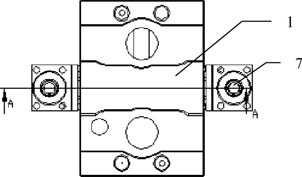
[0019] As an embodiment of the robotic gripper of the present invention, see Figure 1 to Figure 5 , comprising a cylinder block 1, a two-way cylinder, positioning pins 4 and grabbing nippers 3, the two-way cylinder is arranged on the cylinder block 1, a main shaft piston 2 is respectively provided at both ends of the two-way cylinder, and the grabbing nippers 3 Set on the main shaft piston 2, the positioning pin 4 is set on the lower surface of the cylinder block 1, the grasping nipper 3 is provided with a propping mechanism 7, and the propping mechanism 7 includes a propping cylinder 71 and a propping Raise the rod 72, and the described prop up rod 72 is arranged on the prop up cylinder 71.

[0020] The specific operation process of the...


PUM


Abstract

The invention relates to a robot claw, which comprises a cylinder body, a bidirectional cylinder, a positioning dowel and grabbing nippers. The bidirectional cylinder is arranged on the cylinder body, two spindle pistons are respectively disposed at two ends of the bidirectional cylinder, the grabbing nippers are disposed on the spindle pistons, the positioning dowel is arranged on the lower surface of the cylinder body, jacking mechanisms are arranged on the grabbing nippers, each jacking mechanism consists of a jacking cylinder and a jacking rod, and each jacking rod is disposed on the corresponding jacking cylinder. When a robot induces that the weight of a grabbed article exceeds rated load of the robot, a control system of the robot transmits a signal to the jacking mechanisms of the robot claw, the jacking cylinders of the jacking mechanisms on two sides of the robot claw act simultaneously, a positioning hole of the grabbed article is released from the positioning dowel of a machining cabinet by the aid of matching of the robot, and accordingly a jig or the grabbed article is stably and vertically released from the positioning dowel on the machining cabinet. In addition, the jacking mechanisms are disposed on the grabbing nippers, accordingly, a space is saved better, and the weight is lightened better.

Description

technical field [0001] The invention relates to a robot gripper. Background technique [0002] The robot grippers circulating in the market are generally only suitable for routine automated production operations. When high-end mobile phone manufacturing industries require high-precision processing or need to grasp some structurally complex parts, they are cumbersome and cannot meet the processing requirements. Taking a robot with a load of 5 kg commonly used in the mobile phone industry as an example, its robot gripper has the following defects: 1. The weight of the robot gripper itself is large, and the weight of the grasped object can easily exceed the theoretical tolerance value of the robot ;2. The positioning pins on the lower surface of the cylinder block cannot be freely set and edited according to the needs; 3. When the friction force between the positioning holes on the object to be grasped and the positioning pins on the processing machine is too large, the robot w...

Claims


Application Information

Patent Timeline
Patent Type & Authority Patents(China)
IPC IPC(8): B25J15/08
Inventor 李杰
Owner 安徽果力智能科技股份有限公司
Learn More