Method for preventing nitrogen increase of molten steel in LF (Ladle Furnace) refining process by top-blowing argon gas

A refining process and top blowing technology, applied in the field of metallurgical technology, can solve problems such as increased cost, large amount of slag, unfavorable operation, etc., achieve significant social and economic benefits, and improve the quality of molten steel

Inactive Publication Date: 2012-07-11
UNIV OF SCI & TECH BEIJING +1
View PDF5 Cites 7 Cited by
  • Summary
  • Abstract
  • Description
  • Claims
  • Application Information

AI Technical Summary

Problems solved by technology

Many of the current steelmaking processes use LF furnace refining, but a big problem in the LF furnace refining process is the nitrogen increase in molten steel caused by exposure of molten steel to air and arc ionized air. In order to prevent the nitrogen increase in the LF process At present, the more commonly used technology is the foam slag submerged arc operation technology, but this technology requires a large amount of slag, increases the cost, is not conducive to operation, and the effect is unstable, generally still increases by 5-20ppm, or even more

Method used


Image

  • Method for preventing nitrogen increase of molten steel in LF (Ladle Furnace) refining process by top-blowing argon gas
  • Method for preventing nitrogen increase of molten steel in LF (Ladle Furnace) refining process by top-blowing argon gas

Examples


Embodiment 1

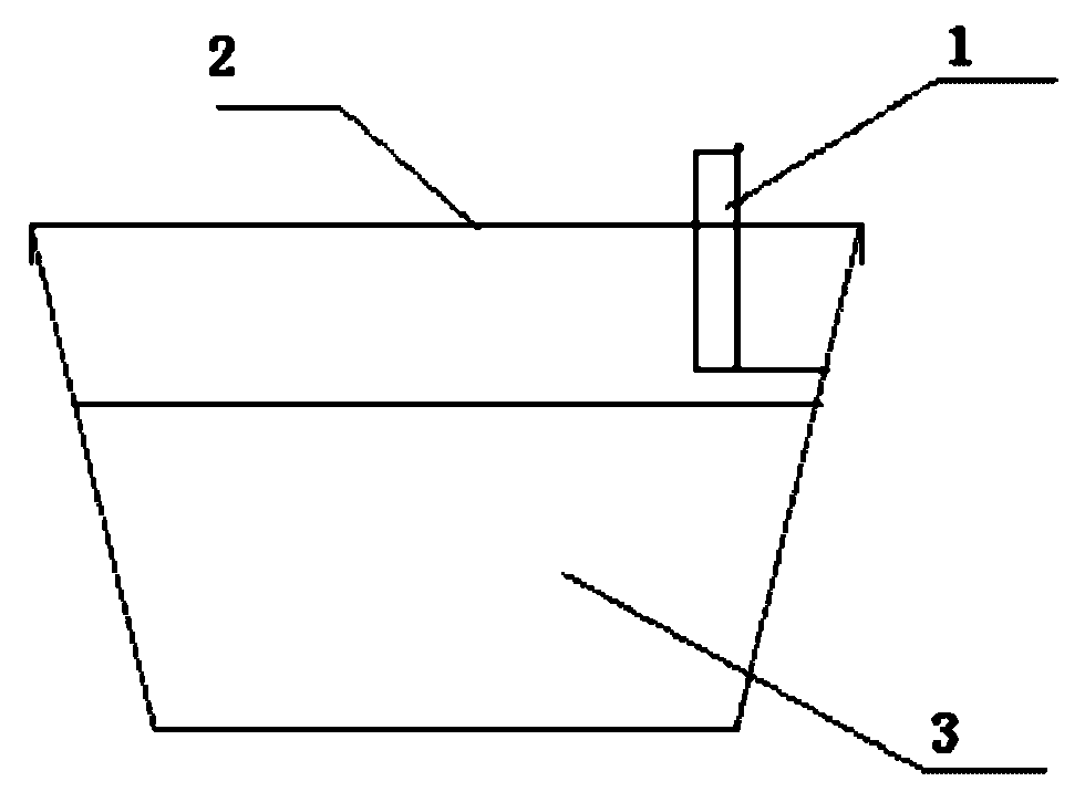
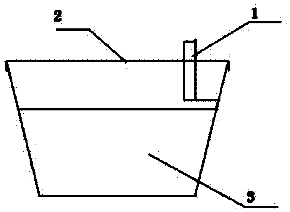
[0017] After the ladle enters the LF processing station, lower the top-blown argon gun to 140mm above the liquid surface, blow in pure argon, the flow rate of the argon gas is 20NL / min, create an inert gas environment, and stably control the amount of nitrogen added to the molten steel to less than 5ppm, carry out normal LF refining treatment, after refining for 75 minutes, the argon gun stops blowing argon, lifts the argon gun, and the ladle leaves the processing station.

Embodiment 2

[0019] After the ladle enters the LF treatment station, lower the accidental argon gun to 170mm above the liquid surface, blow in pure argon gas, and the flow rate of argon gas is 45NL / min to create an inert gas environment, and stably control the amount of nitrogen added to the molten steel to less than 5ppm, carry out normal LF refining treatment, after refining for 47 minutes, stop blowing argon from the argon gun, lift the argon gun, and open the ladle to the treatment station.

Embodiment 3

[0021] After the ladle enters the LF processing station, lower the top-blowing argon gun to 150mm above the liquid surface, blow in pure argon, the flow rate of the argon gas is 80NL / min, create an inert gas environment, and stably control the amount of nitrogen added to the molten steel to less than 5ppm, carry out normal LF refining treatment, after refining for 50 minutes, the argon gun stops blowing argon, lifts the argon gun, and the ladle leaves the processing station.

[0022] Table 1 Example of LF anti-nitrogen production process

[0023] serial number N content in front of LF furnace, wt% N content after LF, wt% Nitrogen addition, wt% 1 0.0023 0.0028 0.0005 2 0.0022 0.0024 0.0002 3 0.0026 0.0027 0.0001


PUM


Abstract

The invention belongs to the field of a metallurgical technology, particularly provides a method for preventing nitrogen increase of molten steel in LF (Ladle Furnace) refining process by top-blowing argon gas. In the LF refining process, pure argon is top blown with an LF top-blow argon gun or an LF accident argon gun at a site 140-170mm from the surface of molten steel at a flow rate of 20-80NL/min to create an inert gas environment, so as to stably control the amount of nitrogen increase smaller than 5ppm. The method of the invention has the following advantages: low-slag refining is adopted to reduce cost; the requirement for operation is simple; the impact on process is low; the original LF accident argon gun is utilized, so that no equipment needs to be additionally provided; the refining time needs not to be deliberately compressed in order to reduce nitrogen absorption, other refining effects are not influenced, and the quality of molten steel is improved; and the method has significant social and economic benefits.

Description

technical field [0001] The invention belongs to the field of metallurgical technology, and in particular provides a method for preventing nitrogen increase in molten steel during LF refining by top blowing argon. Background technique [0002] The nitrogen content in the steel affects various properties of the steel, such as cold bending performance, impact toughness, etc. With the higher and higher material performance requirements, the demand for low nitrogen steel is increasing, and the nitrogen content in the steel is required to be ≤50ppm (mass score, 10 -4 %). In order to produce low nitrogen steel, tighter control of the nitrogen content of the steelmaking process is required. Many of the current steelmaking processes use LF furnace refining, but a big problem in the LF furnace refining process is the nitrogen increase in molten steel caused by exposure of molten steel to air and arc ionized air. In order to prevent the nitrogen increase in the LF process At present...

Claims


Application Information

Patent Timeline
Patent Type & Authority Applications(China)
IPC IPC(8): C21C7/072
Inventor 岳峰吴华杰崔衡杜建新陈勇冯美兰
Owner UNIV OF SCI & TECH BEIJING
Why Eureka
Try Eureka