
Magnetic core heat treatment clamp

A magnetic core and fixture technology, applied in the manufacture of inductors/transformers/magnets, electrical components, circuits, etc., can solve the problem of low magnetic core occupancy, and achieve the effects of good molding quality, high strength and good heat treatment quality.

Inactive Publication Date: 2012-07-11
NAT SPACE SCI CENT CAS
View PDF2 Cites 6 Cited by
  • Summary
  • Abstract
  • Description
  • Claims
  • Application Information

AI Technical Summary

Problems solved by technology

The traditional method of preparing the magnetic core is to stack the strip-shaped magnetic core diaphragms successively in multiple layers and then directly bundle them with metal wires or press the stacked multi-layer strip magnetic core diaphragms into a sheet and fold them into metal plates. In the long slot with a rectangular cross section, heat treatment is carried out to shape the shape, but there are disadvantages of secondary shaping of the magnetic core diaphragm after heat treatment and low duty ratio of the magnetic core in the coil.
Therefore, the traditional magnetic core production has not used a complete set of special heat treatment equipment such as the magnetic core shaping jig used in this patent, especially in the heat treatment. Therefore, compared with similar foreign instruments, there will be differences in both test performance and detection data comparison. A certain obvious gap is also an inevitable result. For this reason, it is extremely necessary to develop a key equipment such as a molding die for heat treatment of the magnetic core.

Method used


Image

  • Magnetic core heat treatment clamp
  • Magnetic core heat treatment clamp
  • Magnetic core heat treatment clamp

Examples


Embodiment Construction

[0031] The present invention will be further described below in conjunction with the accompanying drawings and specific embodiments, and realized through the following technical solutions.

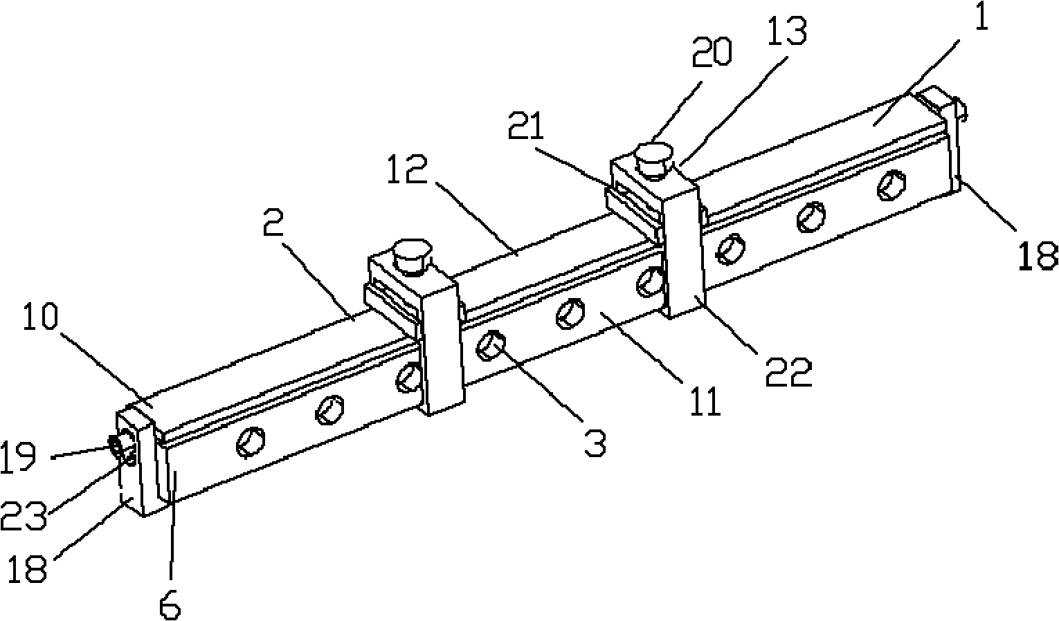
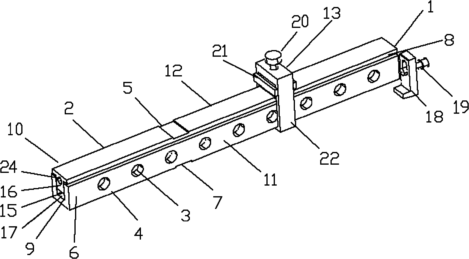
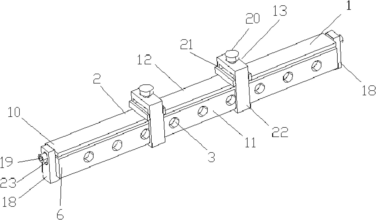
[0032] Such as figure 1 As shown, a magnetic core heat treatment jig of the present invention includes: a magnetic core heat treatment molding die 1 and a fastening fixture 14; The groove pressing part 12 includes a pressing plate 2 and an L-shaped fastener 18 fixed on the end of the pressing plate. The main body of the fastening fixture 14 is a combination of locking fixtures 13, and the combination of locking fixtures 13 is composed of a rectangular locking ring 22, an I-shaped The pressing plate 21 and the fastening knob 20 are composed.

[0033] Among them, such as figure 2 Described, described pressing plate 2 is the straight bar of T-shaped cross section, and described section becomes the pressing plate 2 of T-shaped cross section, and the lower half 8 of pressing plate on the ver...


PUM


Abstract

The invention relates to a magnetic core heat treatment clamp. The clamp comprises a magnetic core forming die (1) and a combined fastening clamp (14), wherein the magnetic core forming die (1) comprises a concave slot body (11), a pressing plate (2) matched with a concave straight slot (15) of the concave slot body (11) and an L-shaped fastener (18) fixed at the end part of the pressing plate, wherein two side walls (6) of the concave slot body (11) are respectively provided with a group of air holes (3), and the fastening clamp (14) as a combination of locking and fastening clamps (13) is used for clamping the concave slot body (11) and the pressing plate (2). The magnetic core heat treatment clamp has the advantages of reasonable whole structure, small deformation, suitability for working at high temperature for a long term, uniformity in force borne by a whole membrane, good forming quality of a magnetic core rod structure, precise size, small error, reasonable arrangement of a ventilation structure of the heat treatment clamp, good ventilation effect, good membrane heat treatment quality and no impurity pollution to a magnetic core membrane of the magnetic core heat treatment clamp made of the same material under a high-temperature environment.

Description

technical field [0001] The invention relates to the field of magnetic core preparation, in particular, the invention relates to a jig for heat treatment of a magnetic core. Background technique [0002] Since the space-borne magnetic wave space probe carried on the space science satellite needs to have high sensitivity to extract the extremely weak low-frequency wave signal in the space magnetosphere in a very high background interference noise level, the instrument itself, especially its Key devices such as sensor search antennas require extremely meticulous design and production, which firstly includes the sensor search antenna or the magnetic core components of the magnetic wave detection coil that can greatly enhance the induced magnetic field signal, and enhance the magnetic permeability of the magnetic core and improve the magnetic core. It is particularly important to increase the relative duty cycle of the magnetic core in the cross-section of the detection coil and ...

Claims


Application Information

Patent Timeline
IPC IPC(8): C21D1/00H01F41/02
Inventor 董伟沈超陈涛王作桂路立
Owner NAT SPACE SCI CENT CAS
Learn More